Archives for posts with tag: demo

The best way to explain MDE to someone without any model-driven experience is to involve in an MDE development. The second best, for which blog is a suitable medium, is to show examples. Today I would like to share an example of a simple MDE application and give a glimpse into work items and a process behind its development.

The application in question is an MDE implementation of a sequencing system described in [1]. The purpose of this MDE exercise was to quickly build something concrete that would help Luminis learn a new vertical domain.

Problem Domain and Demo System

Curriculum content sequencing (CCS) is an important pedagogical service. The purpose of this service is management of learning routes to help students achieve curriculum goals. An emerging trend in education is adaptive learning that is tailored to backgrounds and preferences of individual students. This is in contrast to the traditional way of content sequencing that usually prescribed a single learning route for groups of individuals. Advances in e-learning provide an excellent platform for adaptive content sequencing.

Actors_and_services

Figure 1: Use case diagram of the demo system

A use case diagram in Figure 1 shows actors and important services of a simple content sequencing system. These services are:

Capture sequencing content provides Sequencing Expert with tools to design content sequencing knowledge necessary to reach a curriculum goal. 

Register learning units enables Materials Provider to connect leaning materials to nodes of content sequencing.

Suggest a learning route provides Student with a learning route tailored to the student’s curriculum competences, background and preferences. The service also suggests necessary learning units and their substitutions from other providers.

Problem Domain Ontology

Domain ontology is conceptualization of domain knowledge. Figure 2 shows an information model that captures ontology for the CCS domain. The model is created using the Object Role Modelling (ORM) methodology. Some readers may be also familiar with ORM’s close relatives from The Netherlands: NIAM and FCO-IM.

Simple_ssc_ontology

Figure 2: Ontology for the curriculum content sequencing domain

At this point a few disclaimers are due:

The model loosely conforms to ORM, namely main principles are followed, used notation is based on more popular UML and ER languages, and not all ORM tools are being employed (an example of an ORM tool in Figure 2 is relationship ‘succession’ that is objectified as an entity).

The model itself is not complete. Moreover, it cannot be claimed correct, as the model was not verified with subject matter experts. However, the model is sufficiently accurate for the purpose of the demo (see above).

Design

The system illustrated in Figure 1 is partitioned in 2 parts: a domain specific modeling environment (DSME) for Sequencing Expert and a web-based CMS for Student and Materials Provider. Both parts can import/export curriculum content sequencing designs from each other. Each part provides the actors with rich environment and enables reuse of generic services that are relevant to the application, e.g. user management, document flow, security, content search. Any application-specific functionality that changes frequently during the application’s life-cycle was engineered with models, otherwise programmed. Such points of frequent change are known as variation points.

Figure 3 shows the system parts, variation points (shown as boxes) and activities (diamonds) related to changes in the variation points. These are laid over the OMG’s four modeling layers (labeled M0-M3). Variations at level M1 are part of the normal application operation. Here Sequencing Expert and Materials Publisher define sequencing designs and learning units (LU) respectively. Variations at level M2 occur when domain definitions (see Figure 2) change, e.g. as developer’s understanding of the CCS domain evolves. These are changes to the system itself and are carried out by developers during development or consequent system updates. Grayed out shapes at M0 and M3 are system and technology related variation points that do not change once chosen.

Ccs_meta_application_pim

Figure 3: System parts, modeling architecture, variation points and change processes

Changes at level M2 are expensive and (given the experimental nature of the demo) frequent. Therefore these are best reduced or avoided. The direction of development activities implies that there is a single source of M2 changes, from which all the others can be derived. MDE is applied to isolate this source of change within a model (see Metamodel in the figure) and automate related development activities by means of transformations.

The following are selected technologies:

  • AToM3 ─ a language workbench. AToM3 uses Entity-Relationship (ER) and Graph Grammar (GG) as Metalanguage and Transformation definition language respectively. AToM3 is used as language workbench in (model-driven) development and as domain-specific modeling environment (DMSE) for Sequencing Expert.
  • Zope ─ a web application server that is typically used as intranet and extranet server, document publishing system, portal server and platform for collaboration. In this application, Zope provides a web-based CMS for Student and Material Provider.
  • ZCase ─ a model-driven software factory for code generation of Zope document types.
  • Python for development other than model-driven.

With these solutions and technologies in place, the following is left to be developed:

  1. Metamodels for sequencing designs and learning units (see Figure 2).
  2. A transformation bridging the gap between AToM3 metamodels and ZCase, thus forming a complete transformation chain Model→Code.
  3. Import/export routine between AToM3 and Zope
  4. Simple web-interfaces and document search for Student and Materials Provider

The last two items were trivial to implement. Item 2, while simple, requires introduction of new material (namely ER, Class diagrams, Zope, ZCase, Python) for explanation. For these reasons items 2,3 and 4 will not be covered in the article.

Capturing Sequencing Designs

With the selected technology we can now define a DSL for capturing sequencing designs in AToM3.

Sequencing_dsl_metamodel

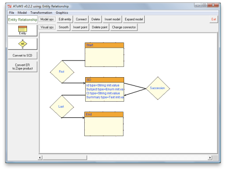
Figure 4: CCS metamodel

Figure 4 shows a CCS metamodel written in ER. Note, that the screenshot shows only the abstract syntax, but the other aspects (see metamodelling quality) are defined as well. The quality of the metamodel is at level 5.

Using language workbench capabilities and the above metamodel, AToM3 configures itself into a dedicated modeling environment for curriculum expert. (This configuration is implemented by AToM3’s own transformation Generate DSME.)

A_learning_sequence_example_of_the_first_grade_mathematics_course_determined_by_curriculum_experts

Figure 5: A learning sequencing design for the first grade mathematics course

Figure 5 is a screenshot of the CCS modeling environment at work: Left vertical toolbar contains buttons for every modeling concept defined in the CCS metamodel. Top horizontal toolbar contains generic modeling tools, Edit and Connect in particular. In AToM3 modeling is performed by means of a visual editor: one selects a modeling concept, places it on the canvas and modifies its properties with the Edit tool. Further on, such created instances of modeling concepts can be coupled using the Connect tool. An example of such a visual model is a sequencing design for the first grade mathematics course, shown on the canvas of DSME.

Sequencing Designs in CMS

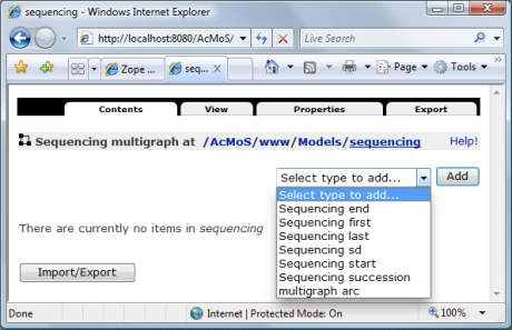
Given the CCS metamodel, transformation chain ER→Zope generates implementation of the corresponding document types for Zope. Figure 6 shows these document types as seen in CMS (see options in the drop down list). You may recognize the entities and relationships from the metamodel shown in Figure 4.

Cms_sequencing_document_types

Figure 6: Sequencing document types available in CMS

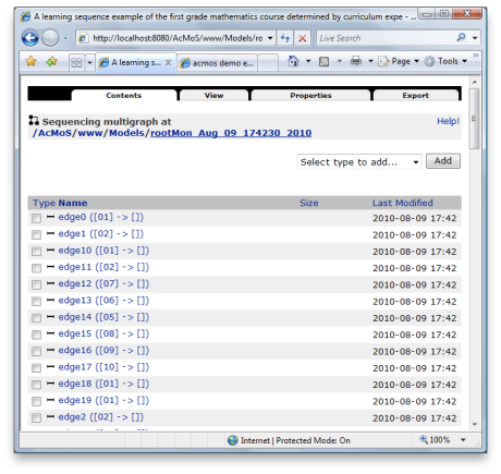
These types allow curriculum experts to build sequencing designs in a web browser. A more convenient way is to transfer sequencing designs from the DSME part. This is achieved by executing an export transformation on a sequencing design in AToM3. The result of this transformation is a fully searchable CCS document stored as graph structure in Zope. For example, given the AToM3 model in Figure 5, export would create a Zope document of type Sequencing multigraph as shown in the figure below.

Author_view_on_a_sequencing_model

Figure 7: Sequencing expert view on a CCS document

Figure 7 shows the web-interface that represents a CCS document as graph structure, i.e. a set of edges and nodes. (A viewer which can display graph-like structures in HTML web pages would be more appropriate, but is not necessary for this demo.) Note that the structure and properties of the AToM3 model from Figure 5 are transferred without loss of information.

The document shown in Figure 7 can be changed online and downloaded (via export tab seen in the screenshot) as an AToM3 model. Consequently, the downloaded file can be loaded in AToM3 for editing, thus closing the import/export round-trip.

Learning Unit Registration

Learning_unit_model

Figure 8: Learning Unit metamodel

Learning Unit is a simple and atomic Zope document type, whose AToM3 metamodel is shown in Figure 8. LU Zope type is generated and its instances are created, searched, read, and modified similar to those of the CCS document types. A simple web interface is sufficient for Material Provider. 

Obtaining Learning Routes

Currently, this service has a very basic recommendation mechanism:

  • Sequencing designs are searched to match query parameters. 
  • No account is taken of student’s curriculum competences, background and preferences (and there is no student profile). 

Searching_for_course_sequencingReader_view_on_a_sequencing_modelSubstitutive_materials_per_sd

The above screenshots illustrate the current functionality: The first is the web interface that allows students to define search parameters and displays search results. The next is the web view of the sequencing design previously shown in Figure 5. Selecting any node of the design, will display information about the sequencing node and suggest learning units and their substitutions from alternative materials providers (see the last screenshot).

Summary

In conclusion, I would like to highlight a few points about this MDE application:

The complete development of the application took about 2 man-week. The real power, however is how fast the application can be updated as the knowledge of the application domain evolves: a matter of an hour given even drastic changes in metamodels. This efficiency is possible due to application of the SSoT principle, proper abstractions and automation: Effectively, two separate PSM developments were replaced by a single PIM development, from which code is generated for two platforms (AToM3 and Zope).

In development of this application, off-the-shelf MDE frameworks were reused (namely AToM3 and ZCase) and traditional development process was interwoven with development of missing model-driven assets (metamodels, ER→ZCase transformation). The latter is a software development process too, and as a matter of fact, followed OMG’s CIM/PIM/PSM process architecture.

Naturally, development of model-driven assets has its particularities as well. For one, there is a much stronger isomorphism between objects in the world of application users and domain concepts in model-driven artifacts. Therefore, role of analysis models, such as shown in Figure 2 is more important than in the more requirements-oriented traditional development.

This demo provides extremely simplified service for learning route recommendation. Recommendation algorithm depends on the information structures and is sensitive to changes in those structures as well. The service is in fact a model interpretation, where model is a CCS design and a Student profile. A possible MDE approach to building an application-specific interpreter is described here (but be sure to read the approach’s limitations as well).

Developed metamodels reach level 5 of metamodeling quality. This topmost level means that all aspects of the language have been modeled, including its semantics. In this demo, semantics of ER was defined by using the translational approach, that is by translating ER concepts to Zope and AToM3 concepts that have precise semantics. Figure 3 shows these translations as Model→Code and Generate DSME activities. This illustrates that a language can have multiple semantics.

The demo also showed that modular transformations can be reused to form new transformation chains. Case in point is how ZCase was integrated in ER to Zope transformation by means of a relatively simple bridge. This is a counterexample to a claim that MDE solutions are inflexible.

Do you have experience with MDE applications within your organization? Can you share these experiences as well?

References

[1] Yu-Liang Chi. 2009. Ontology-based curriculum content sequencing system with semantic rules. Expert Syst. Appl. 36, 4 (May 2009), 7838-7847. 

Blogs by Johan den Haan, Stefano Butti and Jordi Cabot raised interesting discussions about code generation (CG) and model interpretation (MI). One observation I took from these discussions is that MI is still little known. Previously I demonstrated operation of a custom-made model interpreter for a so-called weighbridge domain. Today I would like to share my experience of building this interpreter in a model-driven way.

MDE Approach

Two main choices underpin the process and technology used to develop the interpreter:

  1. Execution semantics of the interpreter is defined within the problem domain itself (weighbridge in this case), without translating it to another domain (e.g. .Net or Java) as it is the case with CG. Such definition of semantics is also known as operational semantics. The advantage is reduction of development complexity: out of at least 2 domains needed for CG, only one and the more abstract domain is sufficient.
  2. Operational semantics is defined within an MDE framework. This enables customization of modeling language for problem domains besides that of the weighbridge example. Moreover, transformation capabilities are used to define operational semantics. 

Domain-specific_nested_interpretation_mde_framework

Figure 1: Domain-specific, nested interpretation (DSNI) MDE framework

Figure 1 shows the MDA framework [1] after it has been adapted to reflect the above mentioned choices. (If you are confused between MDA and MDE, you might find this article useful.) In contrast to MDA, there is no PIM or PSM model, but single computational independent model (CIM) written in DSL. CIM is both source and target of Transformation Tool. Transformation Tool carries out transformation classified as same language, same model. Transformation Definition defines operational semantics. It is not important if Transformation Definition Language (TDL), extends the Metalanguage as in MDA or is customizable by means of meta-specification. Therefore TDL is omitted from the framework and TDL selection criteria are defined instead (see below). Finally, new concept System Context is connected to Transformation Tool. This is due to the fact that interpretation as system exhibits external behavior through communication with other systems.

This approach can be described as nested interpretation, where a domain-specific interpreter is executed (nested) by a generic interpreter. From this perspective, Transformation Tool assumes the role of a generic interpreter and execution of Transformation Definition fills in the role of the domain-specific interpreter.

TDL Selection Criteria

Selection criteria for transformation definition language are:

  • declarative modeling 
  • support for domain-specific notation

These criteria help to reduce development complexity and improve communication with problem domain experts.

Selected MD Technology

AToM3 is a free language workbench written in Python and under development at the Modelling, Simulation and Design Lab (MSDL) in the School of Computer Science of McGill University. The workbench closely matches the DSNI framework and meets the TDL selection criteria. 

In AToM3, DSLs and models are described as graphs. From a language specification written in the metalanguage (ER formalism), AToM3 generates a tool to visually manipulate (create and edit) models written in the specified DSL. Model transformations are performed by graph rewriting. The transformations themselves can thus be declaratively expressed as graph-grammar models. However, AToM3 provides no communication infrastructure as needed by the framework.

Proof of Concept

As demonstration, a language specification for the weighbridge domain was defined (see sections domain and weighbridge DSL here) and graph rewriting was used to model operational semantics (see below). Source code of AToM3 itself, being written in Python, was extended to support web services for the communication purpose.

Operational Semantics

As blueprint for operational semantics of the interpreter, we took πDemos [2], a small process-oriented discrete event simulation language. There is a number of πDemos events that change state of a weighbridge system. For each such event, [2] defined the transitions induced on system state. While the original used functional programming language, this work uses graph rewriting and a graph grammar (GG) rule is defined per event.

Priority GG Rule Description
50 importProcess Adds an external vehicle to EL
25 removeProcess Deletes a vehicle that has completed its todos (events)
40 newR Creates a new weighbridge
40 decP Creates a new vehicle class
40 newP Creates a vehicle from a vehicle class
40 getR Acquires a non-busy weighbridge
40 blockProcess Blocks a vehicle acquiring a busy weighbridge
40 promoteProcess Unblocks a delayed vehicle
40 useR Moves a vehicle on a weighbridge until service is complete
30 releaseResource Moves a served vehicle from a weighbridge to EL
41 putR Releases an occupied weighbridge

Table 1: Graph grammar rules of weighbridge events

Table 1 lists the minimum set of required events and their corresponding GG rules. Execution of such rules needs to be globally orchestrated through proper sequencing. The rules, together with execution sequencing, form an operational semantics model of the interpreter. 

For complete description of the model, please refer to [3]. In the following, we present a detailed description of an example rule, followed by the execution sequencing model.

Example GG Rule

LhsRhs

Figure 2: Subgraphs of the promoteProcess rule

Rule promoteProcess releases a busy weighbridge (bluish box in Figure 2.1) that delays at least one vehicle (yellow box labelled 5). In the new state, the weighbridge remains busy and the blocked vehicle (5) is removed from the head of queue Delay and inserted in waiting queue EL.

The rule is executed if:

  1. The left-hand side (LHS) shown in Figure 2.1 is matched in the host graph (the CIM model).
  2. Associated condition is true: the weighbridge in LHS is the one referred to in the imminent event putR (a todo) in the body (a todo list) of the first vehicle (label 21) in queue EL.

If the above holds, the matched part of the CIM model is substituted with the right-hand side (RHS) shown in Figure 2.2. Note new objects are labelled 10, 11, 13. The entities and relationships in RHS are initialized as follows:

  1. Objects copied from LHS keep all their properties. 
  2. Imminent event putR (a todo)  of the current vehicle (21) is completed. 
  3. All properties of blocked vehicle (5) are copied to vehicle (10).

Execution Sequencing

The execution sequencing is based on the next-event approach: Next event to execute is always the imminent event in the body of the current vehicle. Informally, the operational semantics of execution sequencing is as follows: if EL is empty, interpreter idles until at least one vehicle is inserted in EL. Such vehicle becomes current. If the body of the current vehicle is empty then it is removed from EL and EL is examined again. Otherwise, interpreter  executes a GG rule corresponding to the imminent event of the current and EL is examined again. Note that whenever interpreter is idle, EL is being updated with new vehicles that meanwhile might have arrived from system context.

The execution sequencing is implemented by organizing GG rules into groups, each group having its own base priority. These groups, in the descending order of priority are: vehicle removal, weighing activities and vehicle arrival. Within a group, each rule is assigned a relative priority. If pattern matching of two and more rules within a group is deterministic on the basis of LHSs and conditions, then these rules can share the same priority level. Example rule priorities are given in Table 1.

Conclusion

The demonstrated development approach is characterized by a very high level of abstraction, direct involvement of problem domain experts and absence of software development. All these factors contribute to fast development times: The lead time of this one man project including research and development was 3 weeks. Admittedly, tests of the produced model interpreter showed noticeable performance penalty due to 1) repurposing of MD technology that was not designed for use as interpreter and 2) the overhead introduced by nested interpretation. In my opinion there is much room for performance improvement and I am wondering if MDE can prove useful again. An important message from this experience is that model interpretation does not have to be prerogative of big commercial tools and can get closer to code generation in terms of accessibility.

References

[1] Anneke G. Kleppe, Jos Warmer and Wim Bast. “MDA Explained: The Model Driven Architecture: Practice and Promise”. Addison-Wesley Longman Publishing Co., Inc., Boston, MA, USA, April 2003.

[2] Graham Birtwistle and Chris Tofts. “An operational semantics of process-oriented simulation languages: Part 1 πDemos”. ACM Transactions on Modeling and Com- puter Simulation, 10(4):299–333, December 1994.

[3] Andriy Levytskyy. “Model Driven Construction and Customization of Modeling & Simulation Web Applications”. PhD thesis, Delft University of Technology, Delft, The Netherlands, January 2009.

Model interpretation approach is grasping attention of the model driven community. Industrial experiences of company Mendix has shown some very promising results. A recent post at a popular “model-minded” blog triggered a discussion about code generation versus model interpretation. Model interpretation in itself is not a new concept and there exist well known interpreters for generic and mainstream domains (e.g., Ptolemy and Simulink). The novelty in model interpretation today is that model driven methods provide efficiency and flexibility, which enable application of this concept to arbitrary problem domains. In a series of blogs we will illustrate this novel aspect and provide an example of model interpretation. Specifically this article will illustrate 1) how a custom modeling language (DSL) is developed for an arbitrary problem domain and 2) how a system behavior can be specified with the DSL and directly interpreted without any intermediate transformation steps. In a followup article we will show how a custom model interpreter can be efficiently built using a model driven method.

Model Interpretation As System

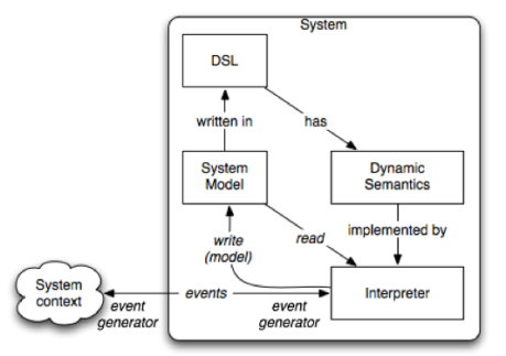
Traditional generative approaches like Model Driven Architecture (MDA) prescribe an (automated) code generation process that takes a system model as input and eventually produces code that implements the specified system. The system comes to existence when the code is executed. Alternatively, the code generation process can be skipped and a system model be executed directly.  Model Interpretation achieves such direct execution by means of a model interpreter. In this case the system comes to existence when the model is being interpreted. Thereby system behavior is completely defined by the model being interpreted. Fig. 1 illustrates a possible approach to model interpretation of event-driven systems.  An event-driven system exhibits behavior by generating (external) events in reaction to incoming external events. Therefore, the interpreter should support two-way event communication with the context. An example of an incoming external event is arrival of a positive signal from a motion sensor for an automated door. An outgoing external event could be a command to an actuator to open the door.

Media_httplsdluminisn_fhrvg

Figure 1: An approach to system as model interpretation In the figure, entities are shown as boxes and their roles w.r.t.  each other are shown in italic. Given that a domain-specific language (DSL) and an interpreter already exist, a domain expert uses the DSL to specify a system and its events at development time. Moving to the run-time, the same model (system configuration) represents the system and its events. During model execution, the interpreter reads system state from the model and interprets system events according to the semantics of the events. Interpretation may change the state of the system by changing the system configuration at run time, and communicate external events to the system’s context. Typically a sequence of external events is provided by the context of the system. Alternatively, these events can be specified in the system model and consequently generated by the interpreter itself (in this case, system behavior is simulated).

Domain

Today model interpretation can be applied to an arbitrary problem domain. To reflect this freedom, we chose a minor and uncommon weighbridge domain, whose purpose is to measure weight of vehicles. The following is a typical weighbridge scenario: One or more delivery vans arriving (at a factory) must pass over a weighbridge on entry. A weighbridge accepts one van at a time and each weighing operation takes a certain amount of time. If the weighbridge is busy, arriving vans join the waiting queue to the bridge. When the weighbridge becomes available again, the first van in the waiting queue drives over the bridge. This domain is characterized by a number of inherent variations, such as number of weighbridges, weighbridge capacity, weighing operation duration, number of arriving vans, arrival times of vans, etc.. The result is that a multitude of weighbridge system configurations are possible and per configuration a multitude of dynamic van arrival and weighing scenarios can play out.

Media_httplsdluminisn_foxbw

Figure 2: A weighbridge system modeled in a DSL Figure 2 shows a simplified weighbridge system configuration, originally described by Birtwistle and Tofts [1]. Yellow boxes are vans. The large blue box is a weighbridge and green entities are a van arrival queue (EL) at the factory and a van waiting queue (Delay) at a weighbridge. As you can see the factory’s configuration has a single weighbridge W, which is free at this time. Finally, three delivery vans V1, V2 and Main have arrived (external events). An execution of this model is illustrated further in the article. An AToM3 implementation of a DSL for the domain is briefly described next.

Weighbridge DSL

The earlier mentioned freedom of application depends on flexibility and efficient adaptation of model interpreters to new domains. Model driven methods achieve this flexibility through metamodeling. If you are not familiar with metamodeling, you can skip this section as it is not required for understanding the demo. A DSL is defined with abstract syntax, concrete syntax, static semantics and dynamic semantics. (Such a definition is known as metamodel.) Behind every DSL is a modeling paradigm that gives fundamental guidelines for metamodeling. In case of the weighbridge domain, a proper modeling paradigm is Process Interaction [2].

Media_httplsdluminisn_harrk

Figure 3: PI Metamodel For the purposes of this demo, a PI modeling language will suffice  and we will reuse and extend a PI metamodel developed by Juan de Lara [3]. We just have to keep in mind that Process and Resource in Juan’s metamodel correspond to van and weighbridge concepts in the demo domain. The abstract syntax of the PI DSL is illustrated in Figure 3. The concrete syntax of this DSL is illustrated in Figure 2. We skip static semantics (in other words, business rules) as the focus of the domain is interpretation, not domain modeling. The following is a brief description of the key PI concepts: Resource is a synonym for the Weighbridge concept. A weighbridge has the following attributes: Name is a unique identifier of Weighbridge: String State denotes availability of Weighbridge: Enum{idle, busy} Tproc is typical duration of weighing service: Time (used in simulated execution) Capacity denotes capability to weigh multiple vans at the same time: [1..N] Load denotes weighbridge’s capacity occupied with served vans: [0..Capacity] Process is a synonym of the Van concept. A van has the following attributes: Name is a unique identifier of Van: String Tcreation is time-stamp of Van’s arrival event: Time Tinitproc is the start time of weighing operation: Time Tendproc is the end time of weighing operation: Time Body is a sequence of tasks: sequence{task} (tasks examples are bridge access, van weighing, bridge exit, etc.) EVnext is the iterator for tasks in body: [0..N] For simulation purposes, additional concepts are defined: Time is a clock for simulated time. ProcIntGenerator specifies time intervals between van arrivals. Finally, to assist visualization of system state, the original metamodel was extended with additional relationship: manageElement specifies an operation (append, insert or remove) on an element (target end of this relationship) of a sequence (source end of this relationship). The final touch of DSL definition is dynamic semantics (meaning of DSL concepts). In the model interpretation approach, such semantics is defined in an interpreter. In case of a DSL and a pure interpretive approach there is a good chance that an interpreter exactly matching the DSL will need to be developed. More so if the interpreter has to meet additional specific requirements. In our case, such requirements were run-time visualization of system behavior and interpreter integration with the factory context (not covered in this article). In a followup article we will show how a custom model interpreter can be developed. Incidentally our development approach is also based on model interpretation.

Run Time Example

A picture is worth a thousand words. With that in mind an illustration of model interpretation is best done with a video. The following screencast shows execution of the weighbridge system configuration introduced earlier (see Figure 2). For the sake of visualization, execution is carried out in the step-by-step mode and displays how the state of the weighbridge configuration changes in response to events.

Conclusions

In our experience model interpretation is characterized by very fast development times. In fact it did not even feel like development at all as domain experts are completely shielded from all incidental technical details.  I believe that Birtwistle and Tofts, the scientists that coined the weighbridge benchmark, would feel at home with the demonstrated DSL and the interpreter in no time. With incidental complexity out of the equation and direct involvement of domain experts, I think we’ve come very close to the essential complexity of the domain and development times cannot be drastically improved any more. That said, I feel that those interested in this approach should be aware of run-time performance penalty due to interpreter indirection. Whether this will pose a problem, depends on the application domain. What are your experiences with model interpretation? What is your domain?

References

[1] Graham Birtwistle and Chris Tofts. An operational semantics of process-oriented simulation languages: Part 1 πDemos. ACM Transactions on Modeling and Computer Simulation, 10(4):299–333, December 1994. [2] Jerry Banks, editor. Handbook Of Simulation. Principles, Methodology, Advances, Applications, and Practice, pages 813 – 833. Wiley-Interscience Publication, New York, September 1998. [3] Juan de Lara. Simulacio ́n educativa mediante meta-modelado y grama ́ticas de grafos. Revista de Ensen ̃anza y Tecnolog ́ıa, 23, Mayo-Agosto 2002.