Archives for posts with tag: MDD

Recently I came across an interesting article by Jordi Cabot, in which he shares a tool vendor’s experience of high customer acquisition cost for MDD tools. In my opinion the main reason for this is that MDE is still not a mainstream methodology and hence benefits of MDD tools (and what it takes to reach those benefits) are often not clear to customers. This an issue I’ve had to deal with in all MDE-projects and currently in the CHARTER project, where Luminis is involved in industrial evaluation of an MDE tool-chain. In this post I would like to look at the problem from the customer perspective. 

Screen_shot_2012-02-26_at_12

Figure 1: Customer processes and MDE tools

Given a large number and diversity of MDE tools (actually too many, one may argue), it is impractical to list added value cited by their vendors. Moreover, added value is per definition subjective to customer’s opinion. Instead I would like to step back and place these tools in customer’s context. For this I will use a simple classification model that partitions all customer processes and tools supporting them in four quadrants (see the figure). There are two dimensions: uniqueness (core/context) and technology (problem/solution). Core represents unique processes that are specific to a customer, which is in contrast to generic processes in Context. Customer’s business processes are found in category Problem. Solution is reserved for IT or Engineering processes supporting the business processes.

The four quadrants in the figure help to reason about the value of customer processes and tools. The most important are the core quadrants as these define the customer itself. Depending on the type of the customer’s industry, critical processes are found either in the 1st (service-oriented) or the 3rd quadrant (product-oriented). The context quadrants have the least value. Here customers often seek to outsource processes or purchase generic off-the-shelf solutions. 

The following is a summary of MDE value for customers, based on my personal experiences in the four quadrants:

  • Q4 is the hardest to sell. The reason for this is that here MDE provides a generic solution for a solution to a business problem. In other words, an unknown (and therefore regarded risky) MDE tool has to compete against multiple possible solutions that customer is more comfortable with. These include alternative mainstream technologies, in-house frameworks and run-time platforms, and even business changes that may cut ground from under the foot a tool vendor might have in the customer’s door. Warm reception by end users that love tinkering with their own ad hoc productivity solutions, is not guaranteed (not to mention their concern of becoming unneeded). Moreover, any MDE gains achieved in Q4 are likely to be watered down by waste in customer processes elsewhere. Industrial practices show that successful MDE application results in maximum 30%-40% faster overall development. These gains are among the lowest in MDE (compare these with up to 10x acceleration reported in Q1). Moreover, these gains are further relatively reduced when contrasted against alternative solutions. Last but not least, value of the initial gains is the hardest to demonstrate (you may discover that your stakeholders are not even aware of real business problems). The same stakeholders have the weakest influence over budget. It really looks like odds are against MDE tools in this quadrant today. Still, organizations without core processes, e.g. startup customers or customers developing one of a kind systems, may be interested in MDE tools here.
  • Q2: MDE tools are typically not found here.
  • Q3: This is the place of unique processes and numerous stakeholders from various domains: engineering disciplines (software development being one of them), architecturing, system design to name a few examples. Here MDE tools together with process optimizations can produce dramatic overall improvements (especially in product-oriented industries), which can be measured and linked to business needs recognizable by the customer. However, processes here are often knowledge-intensive and free-form, which makes the road towards these improvements longer and more complex compared to Q1, where processes are more structured and information-intensive. Off-the-shelf fixed MDE solutions are at disadvanage here.
  • Q1 is the easiest for customer acquisition. Tool vendors can produce proofs of concepts in really short sprints (typically up to two weeks), deliver never seen before results (e.g. up to 10x faster development), directly relate these results to real business needs (usually falling under the business agility umbrella, but also including the more common T2M and cost reduction benefits) and have the shortest lines to budget holders. It is no wonder that vendors in this quadrant report numerous successes and are even able to grow under currently declining economic conditions.

So what kind of MDE tools are found in these four quadrants? Figure 1 illustrates my attempt to classify the tools. (This classification provides sufficient coverage and is by no means exhaustive.) The categories are: 

  • CIM tools are fixed business modelers with interpretation or code generation capabilities. Modifier CIM (Computation Independent Model) stresses that these tools focus on business solutions and isolate users from developing source code. Well-known examples come from Mendix and OutSystems.
  • OTS are off-the-shelf applications that support generic business processes. Examples include CRM, ERP, Office and Simulation packages.
  • DSM tools are language workbenches that enable customers define their own domain-specific modeling (DSM) and transformation processes. Typical tools in this group are MetaEdit+, Obeo Designer, oAW, AToM3, etc.. Note that while application of DSL tools in quadrants 1 and 2 is not unimaginable due to adaptability of such tools, there is not much “meta-” variability and too much integration complexity to justify such application.
  • PIM tools are fixed UML modeling tools with (generic) code generators for one or more software technology platforms (e.g. .NET, Java, PHP). Modifier PIM (platform-independent model) indicates that users are at best isolated from details and differences of the platforms. Numerous examples can be found be found here.

Since I’ve mentioned the CHARTER project, it would be natural to place its tool-chain (aka CTC) in Figure 1 as well, especially because it presents an exception to the above experiences. CTC provides support for Java source code verification, testing and compilation, which are generic processes, thus placing CTC among PIM tools in Q4. However, due to restrictions that safety critical systems impose on those processes, there are no alternatives currently available. This coupled with huge error costs in such systems, significantly increases the tool-chain’s value for its potential customers.

Conclusion

In conclusion, I agree with Jordi that the cost of customer acquisition is high. However the situation is not the same for all MDE tool vendors. Those behind CIM tools, enjoy impressive interest from business customers. Their successes are responsible for the current breakthrough in popularity of MDE. Life is the most difficult for PIM tool vendors as too many factors may work against their tools in customer context. Moreover, they face competition from more versatile DSM tools. Last but not least, DSM tools can provide impressive benefits in Q3 (especially in product-oriented industries), but require that customer first commits to learning its own often knowledge-intensive processes. In my opinion, this quadrant and DSM tools are the stage for the next MDE breakthrough.

A necessary disclaimer is that the above conclusions are based on my own limited experiences. If you are an MDE tool vendor, customer or MDE professional, I would love to hear your opinion!

Atom3logo

AToM3 is a language workbench developed at the Modelling, Simulation and Design Lab (MSDL) in the School of Computer Science of McGill University. Please note that the reviewed version is not the latest (0.3).

The focus of the review is the language workbench capabilities, that is everything related to specification of modeling languages and automated processing of models.

Freeform Multilingual Modeling

In AToM3, models (and metamodels) are visually described as graphs. There is no support for spatial relationships, such as containment or touch. While position of modeling elements may seem to imply spatial relationships among them (e.g. among a software component and a port), AToM3 does not recognize, maintain or process such relationships.

Modeling is performed by means of a visual editor: one selects a modeling concept from one of possibly multiple language toolbars (to the left of the canvas) and places (instantiates) it on the canvas. Any language toolbar can be easily removed or added by closing or opening its language-specification file. Furthermore, the toolbar itself is defined by a model in a so-called “Buttons” DSL (see Figure 1). At any time, the modeler is free to edit this model to e.g. arrange buttons in one or multiple rows, remove language concepts or specify additional buttons to launch transformations frequently used with the given language. Both language specification and toolbar files are generated by AToM3 from the language model (aka metamodel). Language independent tools like Edit, Connect, Delete form the general modeling toolbar (above the canvas).

Figure_1

Figure 1: A “Buttons” model for a DSL

A special feature of AToM3 is a freeform multi-language canvas. AToM3 breaks with the tradition of “strongly typed” diagrams that prevent intermixing modeling elements if not explicitly allowed by the diagram’s metamodel type. AToM3 canvas can be considered a diagram that allows any modeling elements. However, elements can only be connected if their metamodel allows this. Such canvas provides users with a high degree of modeling freedom. (As illustration of this freedom, AToM3 logo itself is a freeform model done using 5-6 DSLs). Furthermore, because models are not fragmented among islands of diagrams, information access is optimal. Another benefit is less effort on the metadeveloper’s part because a freeform model can be handled by a transformation without the prior need of metamodel integration.

Unfortunately as models grow in size and number, the single canvas does not scale well, nor does AToM3 provide the user with means to manage them.

AToM3 uses this editor and the freeform canvas in a few different contexts. The primary role is a modeling editor, however the same editor is used for metamodeling and specifying transformation definitions. Such reuse reduces the learning curve and more importantly, brings the benefits of a domain specific modeling environment and the freeform canvas to metadevelopers as well.

Language Specification

AToM3’s metalanguage is based on the Entity Relationship (ER) formalism. In order to provide complete metamodeling capabilities, concepts Entity and Relationship are extended with constraints and appearance properties (see Figure 2). Property constraints is used to define static semantics. Appearance defines visual presentation or concrete syntax of a language concept.

Figure_2Figure_3

Figure 2: Features of Entity or Relationship. Appearance editor

AToM3 provides overall excellent metamodeling capabilities that enable metadevelopers produce level 5 quality metamodels. The following details these capabilities.

Abstract Syntax

For this task metadevelopers are equipped with the ER-based metalanguage, which is very close to conceptual modeling techniques, such as ORM. This means that there is a minimum gap between conceptual, business world-oriented models and AToM3 metamodels. In fact, AToM3 abstract syntax models are surprisingly simple and void of technical details typical for metamodels, which makes the models very readable by subject experts. Figures 2 and 4 of the Curriculum Content Sequencing (CCS) demo illustrate this point.

Concrete Syntax

A simple but sufficient editor allows to define a vector presentation for a language concept. Figure 2 shows all that the editor has to offer.

Static Semantics

The constraints property contains rules that control how a modeling element can be connected to another element to form a meaningful composition. Such rules can be defined per language concept or a model and triggered by editor events (e.g. edit, save, transformation start) or on demand by user, thus covering all imaginable ways to invoke model checking.

AToM3 constraint language is Python, which is an unusual choice. Indeed, Python is not a constraint language, not formal (in the model-driven sense), and has side effects (AToM3 is written in Python too). However, my experience with AToM3 showed that none of those are real disadvantages in practice: Python is known for a concise and easy to read syntax and as constraint language, is intended for metadevelopers (who know how to deal with side-effects). In this role, Python proved to be powerful, flexible and efficient.

Dynamic Semantics

AToM3 uses a common approach to define DSL semantics by translating language concepts to concepts in another target domain with predefined dynamic semantics (e.g, C++, Java). This approach is known as translational.

Another less common approach supported by AToM3, is by modeling the operational behavior of language concepts [1]. The operational semantics approach specifies how models can be directly executed, typically by an interpreter. Such specifications are expressed in terms of operations on the language itself, which is in contrast to translating the language into another form. The advantage is that operational semantics are easier to understand and write. The disadvantage is that interpreters are normally not available for DSLs due to the very specific nature of the latter. (For an AToM3 illustration of how to build a custom interpreter in a model-driven way, please refer to this article.)

In AToM3 translational and operational approaches are implemented as transformations.

Transformation

AToM3 employes the graph rewriting approach to transform models. Transformations themselves are declaratively expressed as graph-grammar models. My experience with transformation models written in imperative languages (e.g. QVT Operational, MERL) is that more time is spent figuring out how to navigate host model structure to access right information than actually specifying what to do with this information. Declarative approach like that of AToM3, frees the metadeveloper from having to specify navigation, thus drastically reducing complexity of transformation modeling.

Figure_4_1Figure_4_2Figure_4_3Figure_4_4

Figure 3: A GG transformation model, a rule, an LHS and an element’s properties

To define a transformation in AToM3, one needs to create a graph grammar and specify one of more GG rules. Figure 3 shows a GG model for the export transformation in the CCS demo. Each rule specifies how a (sub)graph of a so-called host graph can be replaced by another (sub)graph. These (sub)graphs are respectively called the left-hand side (LHS) and the right-hand side (RHS). A rule is assigned an order (priority), a condition and an action. In AToM3, conditions and actions are programmed in Python. As in the case with the constraint language, Python performs very well in these roles too.

A special feature of AToM3 is that both LHS and RHS can be modeled with the DSL(s) of the host graph. In fact, the (sub)graph editor is based on the above mentioned model editor, and provides the metadeveloper with the freeform multilingual canvas, customizable language toolbars and transformations. The consequence is that it is very easy to construct sub-graphs and verify them with subject experts.

Figure_5

Figure 4: A host model together with a “parameter” model

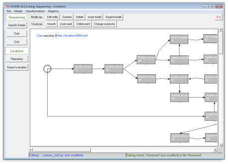
An interesting feature of AToM3 transformation system is that it does not feature transformation parameters. This may seem limiting, however an equally effective alternative is to store “parameter” information in a model. The AToM3 canvas makes it extremely easy to mix such “parameter” model(s) with a host model and pass them to a transformation. Figure 4 shows a sequencing model from the CCS demo together with a repository model (top left corner of the canvas). Given both, an export transformation can access the remote model repository, pass authentication, and store the sequencing model at the repository.

Another interesting feature is that transformation input can be also an element selected by users (unfortunately multiple selection does not work in this version). A promising application thereof is user-defined in-place transformations that automate frequent and routine modeling operations. For example, decomposing a group element into constituent objects (and vice-versa) with a click of a button. Industrial users that often work with large models would really appreciate the resulting reduction of repetitive strain.

Finally, AToM3 supports nearly all transformation kinds known to the author [2, 3]. It is easier to list what is unsupported: text-to-model and text-to-text (which is a consequence of the graphical nature of the language workbench), and the more exotic synchronization and bidirectional kinds. Due to its graph rewriting system, AToM3 is very strong in model-to-model (M2M) and model-to-text (M2T) transformations. A GG-based support for the latter, very popular category, is not obvious and therefore warrants an extra explanation.

M2T Transformation

In AToM3 M2T means producing textual structures from graph structures. One way of doing this is via a transformation where the source and the target models are the same. Rules of such transformation do not perform any important rewriting, but use the graphical nature of the source language to traverse and annotate the source model with temporary information that is needed for text generation. Text itself is generated by side-effects encoded in actions of rules, which can access the annotations.

A typical M2T application is code generation. An example of a non trivial code generation made with AToM3 is ZCase, a software factory for Zope. In the CCS demo, ZCase is a part of the ERZope transformation chain.

Conclusion

The is no escaping the fact that AToM3 is a research tool and is not suitable for demanding industrial use. The workbench does not scale well for large models (both in terms of performance and user controls) and its tools are basic. There is no reliable support, no up-to-date exhaustive documentation, no collaborative development, no integration with version control and requirement management systems, and naturally plenty of bugs and annoyances. In short, the tool is far from being mature and ready for industrial users.

However, metadevelopers may find the above drawbacks quite tolerable, because they are better prepared to deal with technical issues and metamodels typically do not stress the tool’s scalability. On the positive side, AToM3 provides simple but optimal tools and set of features that work together to create one of the most robust and powerful language workbenches I know. Thereby AToM3 is extremely suitable for agile, responsive and timely development. Due to the maturity level of the workbench, its application is best limited to proofs of concept. To date, AToM3 is the language workbench of my choice for quick prototyping.

AToM3 is recommended to MDE students, analysts in need of quick prototyping and tool vendors seeking to improve their language workbenches. In my opinion, AToM3’s metamodeling and transformation technology is nearly optimal, and is still ahead of the larger and more inert commercial workbenches. While its problems are numerous, they are run-of-the-mill and knowledge and technologies to address them are commonly available. If these problems could have been removed, then AToM3 would have been the tool I could have easily recommended to industrial customers too.

References

[1] Tony Clark, Andy Evans, Paul Sammut, and James Willans. Applied Metamodelling: A foundation for Language Driven Development. Version 0.1. Xactium Ltd., 2004.

[2] Krzysztof Czarnecki and Simon Helsen. Classification of model transformation ap- proaches. In Jorn Bettin, Ghica van Emde Boas, Aditya Agrawal, Ed Willink, and Jean Bezivin, editors, 2nd OOPSLA Workshop on Generative Techniques in the Context of Model-Driven Architecture, Anaheim, CA, October 2003. ACM Press.

[3] Tom Mens, Krzysztof Czarnecki, and Pieter Van Gorp. Discussion – a taxonomy of model transformations. In Jean Bezivin and Reiko Heckel, editors, Language Engineering for Model-Driven Software Development, volume 04101 of Dagstuhl Seminar Proceedings, Dagstuhl, Germany, 2005. Internationales Begegnungs- und Forschungszentrum fuer Informatik (IBFI), Schloss Dagstuhl, Germany.

Screen_shot_2011-10-21_at_1

This month, Luminis has started development of a surveillance use case. The purpose of the case is industrial assessment and validation of tools and technologies developed in the “Critical and High Assurance Requirements Transformed through Engineering Rigor” project (CHARTER). The ultimate goal of CHARTER is to ease, accelerate, and cost-reduce the certification of embedded systems. The CHARTER tool-suite employs real-time Java, Model Driven Development (MDD), rule-based compilation and formal verification. The coming series of articles at this blog will describe evaluation experiences in the surveillance use case.

The CHARTER project includes user partners from four key industries: aerospace, automotive, surveillance and medical, each of which develops embedded systems that require high assurance or formal certification in order to meet business or governmental requirements. The four user partners will each validate the CHARTER tools and methodology using industrial applications and actual development scenarios, which will provide feedback for the project and ensure the tools and technologies perform as expected, and deliver the expected improvements in embedded systems development. As part of the evaluation process, metrics will be used to quantify industrial experiences in terms of development effort, cost savings, verification time, etc., to document for others the benefits achieved.

CHARTER is an ARTEMIS JU project that was established to improve the software development process for developing critical embedded systems. Critical embedded software systems assist, accelerate, and control various aspects of society and are increasingly common in cars, aircraft, medical instruments and major industrial and utility plants. These systems are critical to human life and need to be held to the highest standards of performance through formal certification procedures. Improving the quality and robustness of these systems is paramount to their widespread adoption.

Media_httplsdluminise_liblj

MetaEdit+ DSM Environment by company MetaCase is a commercial language workbench that in contrast to inflexible CASE tools, enables users to build their own modeling and code generation tools (aka DSM tools). It comes in two main product components:

  • MetaEdit+ Modeler provides customizable DSM functionality for multiple users, multiple projects, running on all major platforms.
  • MetaEdit+ Workbench i) allows building custom modeling languages (DSLs), and text generators and 2) includes the functionality of MetaEdit+ Modeler and MetaEdit+ API (the latter is not reviewed in this document).

This review is written from the MDE perspective and will cover major MDE functionally related to specification of modeling languages. For a complete picture of MetaEdit+, readers are advised to consider other aspects (e.g. collaboration, versioning, etc…) as well.This review covers MetaEdit+ Workbench version 4.5.

Language Specification

Media_httplsdluminise_qbiie

MetaEdit+ supports graph-like visual languages represented as diagrams, matrixes or tables. There is a limited support for spatial languages: touch and containment relationships are derived from canvas coordinates of modeling elements. There is no actual tool support to preserve these relationships: for example, as a modeller moves a “container” element, contained elements do not move along as expected, but remain at old coordinates.In MetaEdit+, languages are specified with a set of specialized tools. In the following, we describe the tools per each aspect of the visual language definition: abstract syntax, concrete syntax, static and dynamic semantics.

Abstract Syntax

This aspect is defined with GOPPRR metatypes. GOPPRR is an acronym for metatypes Graph, Object, Property, Port, Role and Relationship. For each metatype, there is a form-based tool, e.g. Object tool allows specification of object types  and Graph tool allows assembling types produced with the other tools into a specification of abstract syntax. GOPPRR tools support single inheritance.Graph tool also allows linking DSL objects to graphs of other DSLs through decomposition and explosion structures. Furthermore, through sharing language concepts (of any OPPRR metatype) among graphs, DSLs can be integrated so that changes in one model can be automatically reflected in models based on different languages.An alternative to these form-based tools for abstract syntax specification is a visual metamodeling DSL. However, this functionality is best used as easy start-up leading to automated generation of barebone GOPPRR metamodels. Once a language developer changes a GOPPRR metamodel (which is inevitable), visual metamodeling is best discontinued to avoid manual round-trip between the two metamodels.

Concrete Syntax

By default, MetaEdit+ provides generic symbols. However, language developers are free to specify custom symbols for objects, roles and relationships. These symbols are either defined with a WYSIWYG vector drawing tool or imported from vector graphics (SVG) or bitmap files. Symbols can display text, property values and dynamic outputs produced by text generators (more on generators in section M2T Transformation). Moreover, symbols or their parts can be conditionally displayed. Finally, symbols can be reused among different DSLs via a symbol library.MetaEdit+ does not directly support multiple concrete syntaxes per language, which (the lack of such support) is still a common practice among language workbenches. However, its capability to display symbols based on conditions allows to work around this limitation.

Static Semantics

This aspect covers constraints and business rules. The purpose of these rules is to ensure a consistent and valid model.In general, DSM tools should verify a model against the static semantics of its DSL at different times. These times can be classified as ‘live’ (i.e. when a user is modelling) and ‘batch’ (i.e. invoked on events caused by actions such as user demand, model saving or transformation). Furthermore, tool actions following violation of a constraint can be classified as prevention (i.e. a violating action is canceled and a warning message is displayed) or merely informative (i.e. a violating action is allowed, but model will display clues about invalid constructions until the effect of the action is corrected).MetaEdit’s Constraint tool (available from the Graph tool) allows ‘live’ checks against constraints and preventive protection of models (‘live’ and ‘preventive’ in the terms of the above classifications). The tool is very expressive and easy to use, but covers only limited number of types of constraints, namely:

  • object connectivity in a relationship
  • object occurrence in a model
  • ports involved in a relationship
  • property uniqueness

More advanced constraints have to rely on MERL generator (see section M2T Transformation), which can inform users about invalid constructions during modeling (‘live’ and ‘informative’ in the terms of the above classifications). MERL generator can also be used for ‘batch informative’ and ‘batch preventive’ checks: a checking report can be run on demand or included as preventive check before any other transformation is carried out.

Dynamic Semantics

MetaEdit+ can define dynamic semantics through a process of translating DSL concepts to concepts in another target domain with defined dynamic semantics. Examples of target domains in code generation applications are e.g. C++ or Java. A major benefit of language workbenches is that they are capable of automating this and other useful kinds of processes.

PROCESS AUTOMATION

MDE applications need capabilities to automate processes in which models are inputs and outputs. MetaEdit+ provides various levels of support for model-to-model (M2M), model-to-text (M2T) (e.g. in code generation applications) and text-to-model (T2M) (import of legacy code, data type definitions, etc. into models) types of transformations. (The latter transformation type is not reviewed.)

M2T Transformation

Text (and more specifically code) generation is accomplished with Generator tool that can efficiently navigate models, filter and access information, and output text into external files, Generator Output tool and DSL symbols.  All these tasks are specified with imperative language MERL. While MERL is very concise and efficient for most of these tasks, I think that navigation and access tasks are better accomplished in a declarative way.MERL generators are defined per graph type (i.e. per DSL) and can be acquired from supertypes of a given graph type via an inheritance hierarchy. If a generator has to be used for different graph types, then the generator should be defined for the common parent graph type. On the other hand, DSL developer can define new or redefine generators already provided by parent graph types.Finally, MERL provides support for modularization by allowing includes of generators in other generators. Making modular generators pays off well, as there are many reuse opportunities in MetaEdit+: generators can be reused not only for text generation but also in concrete syntax (symbols) and validation/reporting purposes (symbols, generator output tool).

M2M Transformation

Models can be transformed 1) programmatically via the SOAP and WebServices-based API of MetaEdit+ (this option requires product component MetaEdit+ API) or 2) through code generation of an intermediate external representation (in the XML format) and consequent import thereof as new model.These two options amount to a generic support at a minimum level that is commonly provided nearly by all language workbenches. Moreover, code generation of an intermediate representation cannot implement in-place M2M transformations, of which application examples are: model optimization, model layout, model interpretation, model weaving and any repeatable model manipulation in general.

OTHER

  • DSL evolution: MetaEdit+ updates existing models instantly yet non-destructively to reflect changes in DSLs.  The update policy ensures that models created with the older DSL versions are not broken and remain usable with existing generators. Instant update is also very useful when fine-tuning a DSL with end users.
  • According to MetaCase, a MetaEdit+ project can hold over 4 billion objects. A typical project would contain about 40-100 models (graphs).
  • In the multi-user version, users can simultaneously access and share all models within a Repository. Locking is made at the object-level, so several users could collaboratively work on the same model at the same time.
  • Multi-user collaboration in MetaEdit+, product line analysis of commonality and variability and proper separation of concerns reduce the need for version control as it is known in software engineering. Therefore MetaEdit+ does not provide its own versioning system. Best practices for versioning with MetaEdit+ can be found here.
  • Model interoperability: by default, all models and DSLs can be exported in an XML format. The schemas are very simple, which make it easy to post-process such files if needed. Moreover, the M2T transformation capabilities of MetaEdit+ enable DSL developers to easily create custom export generators.

CONCLUSION

MetaEdit+ is a versatile language workbench that enables building high quality visual DSLs for any kind of domain, be it technical or business. Another key quality of MetaEdit+ is efficient DSL/GOPPRR tools, which allow light-weight, agile and fast DSL development and evolution. A testament to this quality is the fact that MetaCase is one of few language workbench makers that routinely designs and builds DSLs in improvisation with audience at conferences, workshops, etc. In my opinion, this impressive productivity is possible because GOPPRR tools are based on paradigms that are optimum for DSL development (DSM for DSM so to speak).Highlights of MetaEdit+ are:

  • Proper level of abstraction: DSL developers are completely shielded from details of how DSM-tools are implemented. DSL development tools focus on essential abstractions for specification of languages and generators.
  • High-levels of automation: DSM-tools are completely and automatically generated from abstract language specifications.
  • High quality of tools: each DSL development task has its own dedicated tool.
  • Numerous enhancements: high integration of tools, non-destructive evolution of languages, inheritance mechanism, reuse opportunities for types, symbols and generators, visual metamodeling, etc.
  • Very cheap introductory license.

Naturally, there are a few drawbacks as well:

  • No specific support for model-to-model transformation.
  • Somewhat limited constraints support.
  • Limited support for spatial relations.
  • Uncommon user interface.
  • Form-based GOPPRR tools prevent a global overview of a metamodel.
  • Expensive  standard licenses.

Code generation applications are the oldest tradition in MDE and this is where MetaEdit+ excels. As MDE discovers new applications, my experience is that the code generation specialization becomes restrictive. Admittedly, it is possible to implement some types of M2M transformations with code generation (via intermediate representation). However, the problem with this workaround is that it introduces accidental complexity both to MDE developers and more importantly to end users (that have to keep repeating the generate/import routine, sometimes complicated by model merge).That said, in my opinion MetaEdit+ gets the big things right. Whether its shortcomings are little things is a subjective matter that is best evaluated in the context of a concrete problem domain.

Media_httplsdluminise_eewij

In MDD explicit knowledge of the domain is crucial for successful development of domain-specific modeling languages (DSML). Yet many starting DSL developers are missing the skill of domain knowledge conceptualization. The main symptoms are difficulty to come up with good language concepts and struggling with levels of abstractions. While language design remains an art, there are a number of paradigms, techniques and guidelines that can make creation of DSLs easier. These helping means are the core of the DSL design tutorial developed at Luminis Software Development. The tutorial was given for the first time during the PPL2010 conference that took place on November 17 & 18 at Océ R&D, Venlo, NL. A small group of participants learned basics of domain analysis, participated in domain definition and implemented a simple metamodel of their own. The general feedback was very positive. The slides for the tutorial can be downloaded here from the Bits&Chips website.

26-10-2013 Update: the slides are now available via slideshare:

Model interpretation approach is grasping attention of the model driven community. Industrial experiences of company Mendix has shown some very promising results. A recent post at a popular “model-minded” blog triggered a discussion about code generation versus model interpretation. Model interpretation in itself is not a new concept and there exist well known interpreters for generic and mainstream domains (e.g., Ptolemy and Simulink). The novelty in model interpretation today is that model driven methods provide efficiency and flexibility, which enable application of this concept to arbitrary problem domains. In a series of blogs we will illustrate this novel aspect and provide an example of model interpretation. Specifically this article will illustrate 1) how a custom modeling language (DSL) is developed for an arbitrary problem domain and 2) how a system behavior can be specified with the DSL and directly interpreted without any intermediate transformation steps. In a followup article we will show how a custom model interpreter can be efficiently built using a model driven method.

Model Interpretation As System

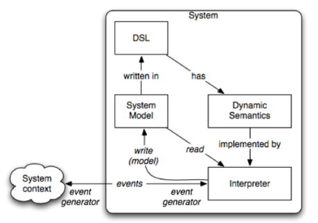
Traditional generative approaches like Model Driven Architecture (MDA) prescribe an (automated) code generation process that takes a system model as input and eventually produces code that implements the specified system. The system comes to existence when the code is executed. Alternatively, the code generation process can be skipped and a system model be executed directly.  Model Interpretation achieves such direct execution by means of a model interpreter. In this case the system comes to existence when the model is being interpreted. Thereby system behavior is completely defined by the model being interpreted. Fig. 1 illustrates a possible approach to model interpretation of event-driven systems.  An event-driven system exhibits behavior by generating (external) events in reaction to incoming external events. Therefore, the interpreter should support two-way event communication with the context. An example of an incoming external event is arrival of a positive signal from a motion sensor for an automated door. An outgoing external event could be a command to an actuator to open the door.

Media_httplsdluminisn_fhrvg

Figure 1: An approach to system as model interpretation In the figure, entities are shown as boxes and their roles w.r.t.  each other are shown in italic. Given that a domain-specific language (DSL) and an interpreter already exist, a domain expert uses the DSL to specify a system and its events at development time. Moving to the run-time, the same model (system configuration) represents the system and its events. During model execution, the interpreter reads system state from the model and interprets system events according to the semantics of the events. Interpretation may change the state of the system by changing the system configuration at run time, and communicate external events to the system’s context. Typically a sequence of external events is provided by the context of the system. Alternatively, these events can be specified in the system model and consequently generated by the interpreter itself (in this case, system behavior is simulated).

Domain

Today model interpretation can be applied to an arbitrary problem domain. To reflect this freedom, we chose a minor and uncommon weighbridge domain, whose purpose is to measure weight of vehicles. The following is a typical weighbridge scenario: One or more delivery vans arriving (at a factory) must pass over a weighbridge on entry. A weighbridge accepts one van at a time and each weighing operation takes a certain amount of time. If the weighbridge is busy, arriving vans join the waiting queue to the bridge. When the weighbridge becomes available again, the first van in the waiting queue drives over the bridge. This domain is characterized by a number of inherent variations, such as number of weighbridges, weighbridge capacity, weighing operation duration, number of arriving vans, arrival times of vans, etc.. The result is that a multitude of weighbridge system configurations are possible and per configuration a multitude of dynamic van arrival and weighing scenarios can play out.

Media_httplsdluminisn_foxbw

Figure 2: A weighbridge system modeled in a DSL Figure 2 shows a simplified weighbridge system configuration, originally described by Birtwistle and Tofts [1]. Yellow boxes are vans. The large blue box is a weighbridge and green entities are a van arrival queue (EL) at the factory and a van waiting queue (Delay) at a weighbridge. As you can see the factory’s configuration has a single weighbridge W, which is free at this time. Finally, three delivery vans V1, V2 and Main have arrived (external events). An execution of this model is illustrated further in the article. An AToM3 implementation of a DSL for the domain is briefly described next.

Weighbridge DSL

The earlier mentioned freedom of application depends on flexibility and efficient adaptation of model interpreters to new domains. Model driven methods achieve this flexibility through metamodeling. If you are not familiar with metamodeling, you can skip this section as it is not required for understanding the demo. A DSL is defined with abstract syntax, concrete syntax, static semantics and dynamic semantics. (Such a definition is known as metamodel.) Behind every DSL is a modeling paradigm that gives fundamental guidelines for metamodeling. In case of the weighbridge domain, a proper modeling paradigm is Process Interaction [2].

Media_httplsdluminisn_harrk

Figure 3: PI Metamodel For the purposes of this demo, a PI modeling language will suffice  and we will reuse and extend a PI metamodel developed by Juan de Lara [3]. We just have to keep in mind that Process and Resource in Juan’s metamodel correspond to van and weighbridge concepts in the demo domain. The abstract syntax of the PI DSL is illustrated in Figure 3. The concrete syntax of this DSL is illustrated in Figure 2. We skip static semantics (in other words, business rules) as the focus of the domain is interpretation, not domain modeling. The following is a brief description of the key PI concepts: Resource is a synonym for the Weighbridge concept. A weighbridge has the following attributes: Name is a unique identifier of Weighbridge: String State denotes availability of Weighbridge: Enum{idle, busy} Tproc is typical duration of weighing service: Time (used in simulated execution) Capacity denotes capability to weigh multiple vans at the same time: [1..N] Load denotes weighbridge’s capacity occupied with served vans: [0..Capacity] Process is a synonym of the Van concept. A van has the following attributes: Name is a unique identifier of Van: String Tcreation is time-stamp of Van’s arrival event: Time Tinitproc is the start time of weighing operation: Time Tendproc is the end time of weighing operation: Time Body is a sequence of tasks: sequence{task} (tasks examples are bridge access, van weighing, bridge exit, etc.) EVnext is the iterator for tasks in body: [0..N] For simulation purposes, additional concepts are defined: Time is a clock for simulated time. ProcIntGenerator specifies time intervals between van arrivals. Finally, to assist visualization of system state, the original metamodel was extended with additional relationship: manageElement specifies an operation (append, insert or remove) on an element (target end of this relationship) of a sequence (source end of this relationship). The final touch of DSL definition is dynamic semantics (meaning of DSL concepts). In the model interpretation approach, such semantics is defined in an interpreter. In case of a DSL and a pure interpretive approach there is a good chance that an interpreter exactly matching the DSL will need to be developed. More so if the interpreter has to meet additional specific requirements. In our case, such requirements were run-time visualization of system behavior and interpreter integration with the factory context (not covered in this article). In a followup article we will show how a custom model interpreter can be developed. Incidentally our development approach is also based on model interpretation.

Run Time Example

A picture is worth a thousand words. With that in mind an illustration of model interpretation is best done with a video. The following screencast shows execution of the weighbridge system configuration introduced earlier (see Figure 2). For the sake of visualization, execution is carried out in the step-by-step mode and displays how the state of the weighbridge configuration changes in response to events.

Conclusions

In our experience model interpretation is characterized by very fast development times. In fact it did not even feel like development at all as domain experts are completely shielded from all incidental technical details.  I believe that Birtwistle and Tofts, the scientists that coined the weighbridge benchmark, would feel at home with the demonstrated DSL and the interpreter in no time. With incidental complexity out of the equation and direct involvement of domain experts, I think we’ve come very close to the essential complexity of the domain and development times cannot be drastically improved any more. That said, I feel that those interested in this approach should be aware of run-time performance penalty due to interpreter indirection. Whether this will pose a problem, depends on the application domain. What are your experiences with model interpretation? What is your domain?

References

[1] Graham Birtwistle and Chris Tofts. An operational semantics of process-oriented simulation languages: Part 1 πDemos. ACM Transactions on Modeling and Computer Simulation, 10(4):299–333, December 1994. [2] Jerry Banks, editor. Handbook Of Simulation. Principles, Methodology, Advances, Applications, and Practice, pages 813 – 833. Wiley-Interscience Publication, New York, September 1998. [3] Juan de Lara. Simulacio ́n educativa mediante meta-modelado y grama ́ticas de grafos. Revista de Ensen ̃anza y Tecnolog ́ıa, 23, Mayo-Agosto 2002.