Archives for posts with tag: MDE

Last week Zest Application Professionals, partner of OutSystems, participated in myNextStep Benelux 2013, a user conference that took place in Chassé Theater in Breda. Read on to find out what I took away from the event.

Innovation

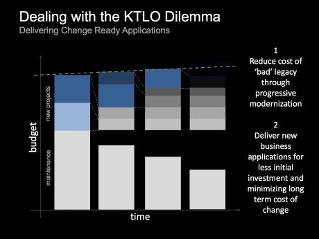
1Ktlo_-_problem_sources2

You may already know that the biggest value of productivity platforms like OutSystems lies rather in reduction of TCO than in savings on the initial application development (although depending on the application, the platform shines there as well). Mike Jones, Chief Evangelist at OutSystems, opened the event with a presentation covering this value, but from a fresh perspective – innovation. This perspective matters because innovation is often associated with a company’s capability to adapt to business demand for change.

The presenter argued that innovating and differentiating applications (in other words applications that are specific to the business and experimental in nature) are in fact the right applications for the productivity platform. More importantly, Mike continued that should packages for these applications be traditionally built, customised or bought, their high TCO over years would eventually deplete budgets allocated for development and maintenance of the application portfolio, thus leaving no room for further innovation.

The core cause for inflated TCO is on one hand – rigidity of commodity applications and on the other – inherently high change frequency of innovation and differentiating processes. The presenter pointed that OutSystems platform enables building for change and thus drives TCO down.

Mike concluded that OutSystems allows businesses to fund innovation though reduced development and maintenance costs.

Usability

43

Usability is the new critical non-functional requirement that is in focus of OutSystems’ R&D. Paulo Rosado, the company’s CEO explained why:

  • Clients no longer compare applications to SAP
  • Tech companies such as Facebook, Zynga, Square are acquiring design studios
  • Business satisfaction is top when delivering a high usability application.

An interesting side effect is that building high usability applications would require more frequent application reviews by end users. In effect, the (less agile) projects may need to adapt to the higher frequency of interaction with business and the need to develop for change would be even more emphasized.

How this awareness will shape the platform is still unclear at this time. Perhaps more information will be revealed at the upcoming OutSystems conference in Lissabon on May 7 & 8, 2013.

Nevertheless, usability of applications can be improved already now with the today’s platform. In a followup track OutSystems shared some design principles and showed how to apply them on the current platform. The resulting screens looked promising – certainly more clean and modern than what I am used to see typically built.

Enterprise Architecture

Built for change is an essential capability of “agile” applications. Naturally, such capability does not come automatically, even if the development platform itself is helping developers. At the event OutSystems shared their best practices with respect to modularity and composition of applications.

4

Given that productivity platforms enable even people without IT background to develope applications, I am glad that this subject receives attention from OutSystem. I hope that they would not stop there. Personally I would love to see the Data DSL become more expressive and Data modelling evolve to Domain modelling (but this is a subject of another post).


If you attended the event too, what topics did you take away? What do you think of the platform? And how should the platform further evolve? 

Images are taken from the event’s presentations.

For the last few years Luminis, a cozy ICT company has been my professional home. I enjoyed much freedom and responsibilities, have worked with some very creative and innovative people, and was privileged to contribute to an impressive MDE success story by a very large industrial client. However MDE as Luminis competence had never grown big enough to become a core business, which eventually and unfortunately led us to a parting of the ways.

Per July 1st I will join Zest Group, a company specialized in business process improvement in Utilities, Industries, Government and Healthcare sectors. A new addition to their arsenal is business engineering empowered by agile model-driven development. This is the area where I intend to contribute in various roles including business engineer, information analyst and modeling coach.

With this change my old wish of applying MDE to business processes comes to a realization. I am also very excited to work with one of the best tools in this area, OutSystems Agile Platform. I consider the fact that it’s becoming possible to have a 100% MDE oriented work, as a long awaited yet cautious sign of MDE commercialization. Whether my expectations will turn true, only time will tell. Nevertheless I am eagerly looking forward to a new start. Wish me good luck 🙂

Change

Due to increasing use of domain specific languages (DSLs), declarative style of modeling is quetly spreading among users of MDE tools. Indeed, it is easy to find examples of declarative DSLs, e.g. at DSM Forums or this blog. There is however a group of users, among which the delarative style of modeling has not managed to spread – transformation developers. I am not sure if it has something todo with the group itself or with the fact that the majority of today’s transformation definition languages (TDL) are still more imperative in style (I am aware of QVT Relations and ATL, but these are rather exceptions than the norm).

There are quite a few good reasons why one would consider using a declarative language for transformation definition: reduction of information content in transformation definitions (and hence higher productivity of transformation developers), more agile DSL evolution, transformation definitions as models, higher compatibility with parallel computing, etc..

Today I would like to share some practical results that illustrate reduction of information content due to use of a declarative language.

CHART vs. Java

The following examples are kindly provided by Maarten de Mol and Arend Rensink from University of Twente. In CHARTER project, they are working on certifiable transformation technology for development of safety-critical embedded systems.

Before proceeding to the examples, here are a few relevant highlights of their technology:

  • Partially declarative transformation definition language (CHART): based on graph transformation and intended to be useable by Java programmers.
  • Transformation compiler (RDT): given a transformation definition written in CHART, generates its executable implementation in Java. The produced code runs against and transforms user provided data.

Figures 1 and 2 present transformation rules findRich and addPicture respectively. Each figure shows its rule written both in CHART and Java. The important Java methods are match() and update(), which are the translations of the similarly named blocks in CHARTER rules. 

Figure_1a_-_findrich_chartFigure_1b_-_findrich_java

Figure 1: Rule findRich written in CHART (a) and Java (b)

In Figure 1a, a match block counts 10 LOC against 41 LOC in Java (Figure 1b), which constitutes a reduction of information content by 75%.

Figure_2a_-_addpicture_chartFigure_2b_-_addpicture_java

Figure 2: Rule addPicture written in CHART (a) and Java (b)

In Figure 2a, an update block counts 12 LOC against 65 LOC in Java, an 80% reduction.

Both examples show significant reduction of information content in CHART rules. The reduction is even stronger if one takes into account that Java implementations also have to address technical concerns, which do not exist in CHART rules. In this case reduction is 92% (13 LOC vs. 160 LOC for rule findRich).

In experence of another CHARTER partner, who evaluates CHART/RDT in practice, a CHART transformation definition counted 1024 lines of code against 8000 in Java, an 87% reduction of information content [1]. Author’s own industrial experiences elsewhere with AToM3 GG rules (declarative) and QVT Operational (imperative) agree with the above results as well.

While exact reduction numbers are certainly arguable, the overal trend in the above experiences is that use of a declarative TDL can result in dramatic reduction of information content and manyfold increase of development productivity.

Conclusion

Despite industrial successes of MDE (which are often hidden), it is my experience that model-driven methods have hard times keeping up as organizations evolve. One factor behing this lag is slow speed of transformation development. Practical industrial experiences such as above, show that declarative languages have potential to significantly improve agility of transformation development.

What are your experiences with declarative TDLs and agile language development? Can you share concrete examples or provide references to declarative TDLs?

References

[1] de Mol, M.J. and Rensink, A. and Hunt, J.J. (2012) Graph Transforming Java Data. In: Proceedings of the 15th International Conference on Fundamental Approaches to Software Engineering (FASE 2012), 26-29 Mar 2012, Talinn, Estonia. Lecture Notes in Computer Science. Springer Verlag.

Recently I came across an interesting article by Jordi Cabot, in which he shares a tool vendor’s experience of high customer acquisition cost for MDD tools. In my opinion the main reason for this is that MDE is still not a mainstream methodology and hence benefits of MDD tools (and what it takes to reach those benefits) are often not clear to customers. This an issue I’ve had to deal with in all MDE-projects and currently in the CHARTER project, where Luminis is involved in industrial evaluation of an MDE tool-chain. In this post I would like to look at the problem from the customer perspective. 

Screen_shot_2012-02-26_at_12

Figure 1: Customer processes and MDE tools

Given a large number and diversity of MDE tools (actually too many, one may argue), it is impractical to list added value cited by their vendors. Moreover, added value is per definition subjective to customer’s opinion. Instead I would like to step back and place these tools in customer’s context. For this I will use a simple classification model that partitions all customer processes and tools supporting them in four quadrants (see the figure). There are two dimensions: uniqueness (core/context) and technology (problem/solution). Core represents unique processes that are specific to a customer, which is in contrast to generic processes in Context. Customer’s business processes are found in category Problem. Solution is reserved for IT or Engineering processes supporting the business processes.

The four quadrants in the figure help to reason about the value of customer processes and tools. The most important are the core quadrants as these define the customer itself. Depending on the type of the customer’s industry, critical processes are found either in the 1st (service-oriented) or the 3rd quadrant (product-oriented). The context quadrants have the least value. Here customers often seek to outsource processes or purchase generic off-the-shelf solutions. 

The following is a summary of MDE value for customers, based on my personal experiences in the four quadrants:

  • Q4 is the hardest to sell. The reason for this is that here MDE provides a generic solution for a solution to a business problem. In other words, an unknown (and therefore regarded risky) MDE tool has to compete against multiple possible solutions that customer is more comfortable with. These include alternative mainstream technologies, in-house frameworks and run-time platforms, and even business changes that may cut ground from under the foot a tool vendor might have in the customer’s door. Warm reception by end users that love tinkering with their own ad hoc productivity solutions, is not guaranteed (not to mention their concern of becoming unneeded). Moreover, any MDE gains achieved in Q4 are likely to be watered down by waste in customer processes elsewhere. Industrial practices show that successful MDE application results in maximum 30%-40% faster overall development. These gains are among the lowest in MDE (compare these with up to 10x acceleration reported in Q1). Moreover, these gains are further relatively reduced when contrasted against alternative solutions. Last but not least, value of the initial gains is the hardest to demonstrate (you may discover that your stakeholders are not even aware of real business problems). The same stakeholders have the weakest influence over budget. It really looks like odds are against MDE tools in this quadrant today. Still, organizations without core processes, e.g. startup customers or customers developing one of a kind systems, may be interested in MDE tools here.
  • Q2: MDE tools are typically not found here.
  • Q3: This is the place of unique processes and numerous stakeholders from various domains: engineering disciplines (software development being one of them), architecturing, system design to name a few examples. Here MDE tools together with process optimizations can produce dramatic overall improvements (especially in product-oriented industries), which can be measured and linked to business needs recognizable by the customer. However, processes here are often knowledge-intensive and free-form, which makes the road towards these improvements longer and more complex compared to Q1, where processes are more structured and information-intensive. Off-the-shelf fixed MDE solutions are at disadvanage here.
  • Q1 is the easiest for customer acquisition. Tool vendors can produce proofs of concepts in really short sprints (typically up to two weeks), deliver never seen before results (e.g. up to 10x faster development), directly relate these results to real business needs (usually falling under the business agility umbrella, but also including the more common T2M and cost reduction benefits) and have the shortest lines to budget holders. It is no wonder that vendors in this quadrant report numerous successes and are even able to grow under currently declining economic conditions.

So what kind of MDE tools are found in these four quadrants? Figure 1 illustrates my attempt to classify the tools. (This classification provides sufficient coverage and is by no means exhaustive.) The categories are: 

  • CIM tools are fixed business modelers with interpretation or code generation capabilities. Modifier CIM (Computation Independent Model) stresses that these tools focus on business solutions and isolate users from developing source code. Well-known examples come from Mendix and OutSystems.
  • OTS are off-the-shelf applications that support generic business processes. Examples include CRM, ERP, Office and Simulation packages.
  • DSM tools are language workbenches that enable customers define their own domain-specific modeling (DSM) and transformation processes. Typical tools in this group are MetaEdit+, Obeo Designer, oAW, AToM3, etc.. Note that while application of DSL tools in quadrants 1 and 2 is not unimaginable due to adaptability of such tools, there is not much “meta-” variability and too much integration complexity to justify such application.
  • PIM tools are fixed UML modeling tools with (generic) code generators for one or more software technology platforms (e.g. .NET, Java, PHP). Modifier PIM (platform-independent model) indicates that users are at best isolated from details and differences of the platforms. Numerous examples can be found be found here.

Since I’ve mentioned the CHARTER project, it would be natural to place its tool-chain (aka CTC) in Figure 1 as well, especially because it presents an exception to the above experiences. CTC provides support for Java source code verification, testing and compilation, which are generic processes, thus placing CTC among PIM tools in Q4. However, due to restrictions that safety critical systems impose on those processes, there are no alternatives currently available. This coupled with huge error costs in such systems, significantly increases the tool-chain’s value for its potential customers.

Conclusion

In conclusion, I agree with Jordi that the cost of customer acquisition is high. However the situation is not the same for all MDE tool vendors. Those behind CIM tools, enjoy impressive interest from business customers. Their successes are responsible for the current breakthrough in popularity of MDE. Life is the most difficult for PIM tool vendors as too many factors may work against their tools in customer context. Moreover, they face competition from more versatile DSM tools. Last but not least, DSM tools can provide impressive benefits in Q3 (especially in product-oriented industries), but require that customer first commits to learning its own often knowledge-intensive processes. In my opinion, this quadrant and DSM tools are the stage for the next MDE breakthrough.

A necessary disclaimer is that the above conclusions are based on my own limited experiences. If you are an MDE tool vendor, customer or MDE professional, I would love to hear your opinion!

Atom3logo

AToM3 is a language workbench developed at the Modelling, Simulation and Design Lab (MSDL) in the School of Computer Science of McGill University. Please note that the reviewed version is not the latest (0.3).

The focus of the review is the language workbench capabilities, that is everything related to specification of modeling languages and automated processing of models.

Freeform Multilingual Modeling

In AToM3, models (and metamodels) are visually described as graphs. There is no support for spatial relationships, such as containment or touch. While position of modeling elements may seem to imply spatial relationships among them (e.g. among a software component and a port), AToM3 does not recognize, maintain or process such relationships.

Modeling is performed by means of a visual editor: one selects a modeling concept from one of possibly multiple language toolbars (to the left of the canvas) and places (instantiates) it on the canvas. Any language toolbar can be easily removed or added by closing or opening its language-specification file. Furthermore, the toolbar itself is defined by a model in a so-called “Buttons” DSL (see Figure 1). At any time, the modeler is free to edit this model to e.g. arrange buttons in one or multiple rows, remove language concepts or specify additional buttons to launch transformations frequently used with the given language. Both language specification and toolbar files are generated by AToM3 from the language model (aka metamodel). Language independent tools like Edit, Connect, Delete form the general modeling toolbar (above the canvas).

Figure_1

Figure 1: A “Buttons” model for a DSL

A special feature of AToM3 is a freeform multi-language canvas. AToM3 breaks with the tradition of “strongly typed” diagrams that prevent intermixing modeling elements if not explicitly allowed by the diagram’s metamodel type. AToM3 canvas can be considered a diagram that allows any modeling elements. However, elements can only be connected if their metamodel allows this. Such canvas provides users with a high degree of modeling freedom. (As illustration of this freedom, AToM3 logo itself is a freeform model done using 5-6 DSLs). Furthermore, because models are not fragmented among islands of diagrams, information access is optimal. Another benefit is less effort on the metadeveloper’s part because a freeform model can be handled by a transformation without the prior need of metamodel integration.

Unfortunately as models grow in size and number, the single canvas does not scale well, nor does AToM3 provide the user with means to manage them.

AToM3 uses this editor and the freeform canvas in a few different contexts. The primary role is a modeling editor, however the same editor is used for metamodeling and specifying transformation definitions. Such reuse reduces the learning curve and more importantly, brings the benefits of a domain specific modeling environment and the freeform canvas to metadevelopers as well.

Language Specification

AToM3’s metalanguage is based on the Entity Relationship (ER) formalism. In order to provide complete metamodeling capabilities, concepts Entity and Relationship are extended with constraints and appearance properties (see Figure 2). Property constraints is used to define static semantics. Appearance defines visual presentation or concrete syntax of a language concept.

Figure_2Figure_3

Figure 2: Features of Entity or Relationship. Appearance editor

AToM3 provides overall excellent metamodeling capabilities that enable metadevelopers produce level 5 quality metamodels. The following details these capabilities.

Abstract Syntax

For this task metadevelopers are equipped with the ER-based metalanguage, which is very close to conceptual modeling techniques, such as ORM. This means that there is a minimum gap between conceptual, business world-oriented models and AToM3 metamodels. In fact, AToM3 abstract syntax models are surprisingly simple and void of technical details typical for metamodels, which makes the models very readable by subject experts. Figures 2 and 4 of the Curriculum Content Sequencing (CCS) demo illustrate this point.

Concrete Syntax

A simple but sufficient editor allows to define a vector presentation for a language concept. Figure 2 shows all that the editor has to offer.

Static Semantics

The constraints property contains rules that control how a modeling element can be connected to another element to form a meaningful composition. Such rules can be defined per language concept or a model and triggered by editor events (e.g. edit, save, transformation start) or on demand by user, thus covering all imaginable ways to invoke model checking.

AToM3 constraint language is Python, which is an unusual choice. Indeed, Python is not a constraint language, not formal (in the model-driven sense), and has side effects (AToM3 is written in Python too). However, my experience with AToM3 showed that none of those are real disadvantages in practice: Python is known for a concise and easy to read syntax and as constraint language, is intended for metadevelopers (who know how to deal with side-effects). In this role, Python proved to be powerful, flexible and efficient.

Dynamic Semantics

AToM3 uses a common approach to define DSL semantics by translating language concepts to concepts in another target domain with predefined dynamic semantics (e.g, C++, Java). This approach is known as translational.

Another less common approach supported by AToM3, is by modeling the operational behavior of language concepts [1]. The operational semantics approach specifies how models can be directly executed, typically by an interpreter. Such specifications are expressed in terms of operations on the language itself, which is in contrast to translating the language into another form. The advantage is that operational semantics are easier to understand and write. The disadvantage is that interpreters are normally not available for DSLs due to the very specific nature of the latter. (For an AToM3 illustration of how to build a custom interpreter in a model-driven way, please refer to this article.)

In AToM3 translational and operational approaches are implemented as transformations.

Transformation

AToM3 employes the graph rewriting approach to transform models. Transformations themselves are declaratively expressed as graph-grammar models. My experience with transformation models written in imperative languages (e.g. QVT Operational, MERL) is that more time is spent figuring out how to navigate host model structure to access right information than actually specifying what to do with this information. Declarative approach like that of AToM3, frees the metadeveloper from having to specify navigation, thus drastically reducing complexity of transformation modeling.

Figure_4_1Figure_4_2Figure_4_3Figure_4_4

Figure 3: A GG transformation model, a rule, an LHS and an element’s properties

To define a transformation in AToM3, one needs to create a graph grammar and specify one of more GG rules. Figure 3 shows a GG model for the export transformation in the CCS demo. Each rule specifies how a (sub)graph of a so-called host graph can be replaced by another (sub)graph. These (sub)graphs are respectively called the left-hand side (LHS) and the right-hand side (RHS). A rule is assigned an order (priority), a condition and an action. In AToM3, conditions and actions are programmed in Python. As in the case with the constraint language, Python performs very well in these roles too.

A special feature of AToM3 is that both LHS and RHS can be modeled with the DSL(s) of the host graph. In fact, the (sub)graph editor is based on the above mentioned model editor, and provides the metadeveloper with the freeform multilingual canvas, customizable language toolbars and transformations. The consequence is that it is very easy to construct sub-graphs and verify them with subject experts.

Figure_5

Figure 4: A host model together with a “parameter” model

An interesting feature of AToM3 transformation system is that it does not feature transformation parameters. This may seem limiting, however an equally effective alternative is to store “parameter” information in a model. The AToM3 canvas makes it extremely easy to mix such “parameter” model(s) with a host model and pass them to a transformation. Figure 4 shows a sequencing model from the CCS demo together with a repository model (top left corner of the canvas). Given both, an export transformation can access the remote model repository, pass authentication, and store the sequencing model at the repository.

Another interesting feature is that transformation input can be also an element selected by users (unfortunately multiple selection does not work in this version). A promising application thereof is user-defined in-place transformations that automate frequent and routine modeling operations. For example, decomposing a group element into constituent objects (and vice-versa) with a click of a button. Industrial users that often work with large models would really appreciate the resulting reduction of repetitive strain.

Finally, AToM3 supports nearly all transformation kinds known to the author [2, 3]. It is easier to list what is unsupported: text-to-model and text-to-text (which is a consequence of the graphical nature of the language workbench), and the more exotic synchronization and bidirectional kinds. Due to its graph rewriting system, AToM3 is very strong in model-to-model (M2M) and model-to-text (M2T) transformations. A GG-based support for the latter, very popular category, is not obvious and therefore warrants an extra explanation.

M2T Transformation

In AToM3 M2T means producing textual structures from graph structures. One way of doing this is via a transformation where the source and the target models are the same. Rules of such transformation do not perform any important rewriting, but use the graphical nature of the source language to traverse and annotate the source model with temporary information that is needed for text generation. Text itself is generated by side-effects encoded in actions of rules, which can access the annotations.

A typical M2T application is code generation. An example of a non trivial code generation made with AToM3 is ZCase, a software factory for Zope. In the CCS demo, ZCase is a part of the ERZope transformation chain.

Conclusion

The is no escaping the fact that AToM3 is a research tool and is not suitable for demanding industrial use. The workbench does not scale well for large models (both in terms of performance and user controls) and its tools are basic. There is no reliable support, no up-to-date exhaustive documentation, no collaborative development, no integration with version control and requirement management systems, and naturally plenty of bugs and annoyances. In short, the tool is far from being mature and ready for industrial users.

However, metadevelopers may find the above drawbacks quite tolerable, because they are better prepared to deal with technical issues and metamodels typically do not stress the tool’s scalability. On the positive side, AToM3 provides simple but optimal tools and set of features that work together to create one of the most robust and powerful language workbenches I know. Thereby AToM3 is extremely suitable for agile, responsive and timely development. Due to the maturity level of the workbench, its application is best limited to proofs of concept. To date, AToM3 is the language workbench of my choice for quick prototyping.

AToM3 is recommended to MDE students, analysts in need of quick prototyping and tool vendors seeking to improve their language workbenches. In my opinion, AToM3’s metamodeling and transformation technology is nearly optimal, and is still ahead of the larger and more inert commercial workbenches. While its problems are numerous, they are run-of-the-mill and knowledge and technologies to address them are commonly available. If these problems could have been removed, then AToM3 would have been the tool I could have easily recommended to industrial customers too.

References

[1] Tony Clark, Andy Evans, Paul Sammut, and James Willans. Applied Metamodelling: A foundation for Language Driven Development. Version 0.1. Xactium Ltd., 2004.

[2] Krzysztof Czarnecki and Simon Helsen. Classification of model transformation ap- proaches. In Jorn Bettin, Ghica van Emde Boas, Aditya Agrawal, Ed Willink, and Jean Bezivin, editors, 2nd OOPSLA Workshop on Generative Techniques in the Context of Model-Driven Architecture, Anaheim, CA, October 2003. ACM Press.

[3] Tom Mens, Krzysztof Czarnecki, and Pieter Van Gorp. Discussion – a taxonomy of model transformations. In Jean Bezivin and Reiko Heckel, editors, Language Engineering for Model-Driven Software Development, volume 04101 of Dagstuhl Seminar Proceedings, Dagstuhl, Germany, 2005. Internationales Begegnungs- und Forschungszentrum fuer Informatik (IBFI), Schloss Dagstuhl, Germany.

Screen_shot_2011-10-21_at_1

This month, Luminis has started development of a surveillance use case. The purpose of the case is industrial assessment and validation of tools and technologies developed in the “Critical and High Assurance Requirements Transformed through Engineering Rigor” project (CHARTER). The ultimate goal of CHARTER is to ease, accelerate, and cost-reduce the certification of embedded systems. The CHARTER tool-suite employs real-time Java, Model Driven Development (MDD), rule-based compilation and formal verification. The coming series of articles at this blog will describe evaluation experiences in the surveillance use case.

The CHARTER project includes user partners from four key industries: aerospace, automotive, surveillance and medical, each of which develops embedded systems that require high assurance or formal certification in order to meet business or governmental requirements. The four user partners will each validate the CHARTER tools and methodology using industrial applications and actual development scenarios, which will provide feedback for the project and ensure the tools and technologies perform as expected, and deliver the expected improvements in embedded systems development. As part of the evaluation process, metrics will be used to quantify industrial experiences in terms of development effort, cost savings, verification time, etc., to document for others the benefits achieved.

CHARTER is an ARTEMIS JU project that was established to improve the software development process for developing critical embedded systems. Critical embedded software systems assist, accelerate, and control various aspects of society and are increasingly common in cars, aircraft, medical instruments and major industrial and utility plants. These systems are critical to human life and need to be held to the highest standards of performance through formal certification procedures. Improving the quality and robustness of these systems is paramount to their widespread adoption.

The best way to explain MDE to someone without any model-driven experience is to involve in an MDE development. The second best, for which blog is a suitable medium, is to show examples. Today I would like to share an example of a simple MDE application and give a glimpse into work items and a process behind its development.

The application in question is an MDE implementation of a sequencing system described in [1]. The purpose of this MDE exercise was to quickly build something concrete that would help Luminis learn a new vertical domain.

Problem Domain and Demo System

Curriculum content sequencing (CCS) is an important pedagogical service. The purpose of this service is management of learning routes to help students achieve curriculum goals. An emerging trend in education is adaptive learning that is tailored to backgrounds and preferences of individual students. This is in contrast to the traditional way of content sequencing that usually prescribed a single learning route for groups of individuals. Advances in e-learning provide an excellent platform for adaptive content sequencing.

Actors_and_services

Figure 1: Use case diagram of the demo system

A use case diagram in Figure 1 shows actors and important services of a simple content sequencing system. These services are:

Capture sequencing content provides Sequencing Expert with tools to design content sequencing knowledge necessary to reach a curriculum goal. 

Register learning units enables Materials Provider to connect leaning materials to nodes of content sequencing.

Suggest a learning route provides Student with a learning route tailored to the student’s curriculum competences, background and preferences. The service also suggests necessary learning units and their substitutions from other providers.

Problem Domain Ontology

Domain ontology is conceptualization of domain knowledge. Figure 2 shows an information model that captures ontology for the CCS domain. The model is created using the Object Role Modelling (ORM) methodology. Some readers may be also familiar with ORM’s close relatives from The Netherlands: NIAM and FCO-IM.

Simple_ssc_ontology

Figure 2: Ontology for the curriculum content sequencing domain

At this point a few disclaimers are due:

The model loosely conforms to ORM, namely main principles are followed, used notation is based on more popular UML and ER languages, and not all ORM tools are being employed (an example of an ORM tool in Figure 2 is relationship ‘succession’ that is objectified as an entity).

The model itself is not complete. Moreover, it cannot be claimed correct, as the model was not verified with subject matter experts. However, the model is sufficiently accurate for the purpose of the demo (see above).

Design

The system illustrated in Figure 1 is partitioned in 2 parts: a domain specific modeling environment (DSME) for Sequencing Expert and a web-based CMS for Student and Materials Provider. Both parts can import/export curriculum content sequencing designs from each other. Each part provides the actors with rich environment and enables reuse of generic services that are relevant to the application, e.g. user management, document flow, security, content search. Any application-specific functionality that changes frequently during the application’s life-cycle was engineered with models, otherwise programmed. Such points of frequent change are known as variation points.

Figure 3 shows the system parts, variation points (shown as boxes) and activities (diamonds) related to changes in the variation points. These are laid over the OMG’s four modeling layers (labeled M0-M3). Variations at level M1 are part of the normal application operation. Here Sequencing Expert and Materials Publisher define sequencing designs and learning units (LU) respectively. Variations at level M2 occur when domain definitions (see Figure 2) change, e.g. as developer’s understanding of the CCS domain evolves. These are changes to the system itself and are carried out by developers during development or consequent system updates. Grayed out shapes at M0 and M3 are system and technology related variation points that do not change once chosen.

Ccs_meta_application_pim

Figure 3: System parts, modeling architecture, variation points and change processes

Changes at level M2 are expensive and (given the experimental nature of the demo) frequent. Therefore these are best reduced or avoided. The direction of development activities implies that there is a single source of M2 changes, from which all the others can be derived. MDE is applied to isolate this source of change within a model (see Metamodel in the figure) and automate related development activities by means of transformations.

The following are selected technologies:

  • AToM3 â”€ a language workbench. AToM3 uses Entity-Relationship (ER) and Graph Grammar (GG) as Metalanguage and Transformation definition language respectively. AToM3 is used as language workbench in (model-driven) development and as domain-specific modeling environment (DMSE) for Sequencing Expert.
  • Zope â”€ a web application server that is typically used as intranet and extranet server, document publishing system, portal server and platform for collaboration. In this application, Zope provides a web-based CMS for Student and Material Provider.
  • ZCase â”€ a model-driven software factory for code generation of Zope document types.
  • Python for development other than model-driven.

With these solutions and technologies in place, the following is left to be developed:

  1. Metamodels for sequencing designs and learning units (see Figure 2).
  2. A transformation bridging the gap between AToM3 metamodels and ZCase, thus forming a complete transformation chain Model→Code.
  3. Import/export routine between AToM3 and Zope
  4. Simple web-interfaces and document search for Student and Materials Provider

The last two items were trivial to implement. Item 2, while simple, requires introduction of new material (namely ER, Class diagrams, Zope, ZCase, Python) for explanation. For these reasons items 2,3 and 4 will not be covered in the article.

Capturing Sequencing Designs

With the selected technology we can now define a DSL for capturing sequencing designs in AToM3.

Sequencing_dsl_metamodel

Figure 4: CCS metamodel

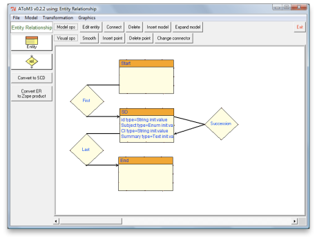
Figure 4 shows a CCS metamodel written in ER. Note, that the screenshot shows only the abstract syntax, but the other aspects (see metamodelling quality) are defined as well. The quality of the metamodel is at level 5.

Using language workbench capabilities and the above metamodel, AToM3 configures itself into a dedicated modeling environment for curriculum expert. (This configuration is implemented by AToM3’s own transformation Generate DSME.)

A_learning_sequence_example_of_the_first_grade_mathematics_course_determined_by_curriculum_experts

Figure 5: A learning sequencing design for the first grade mathematics course

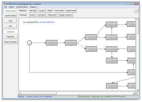
Figure 5 is a screenshot of the CCS modeling environment at work: Left vertical toolbar contains buttons for every modeling concept defined in the CCS metamodel. Top horizontal toolbar contains generic modeling tools, Edit and Connect in particular. In AToM3 modeling is performed by means of a visual editor: one selects a modeling concept, places it on the canvas and modifies its properties with the Edit tool. Further on, such created instances of modeling concepts can be coupled using the Connect tool. An example of such a visual model is a sequencing design for the first grade mathematics course, shown on the canvas of DSME.

Sequencing Designs in CMS

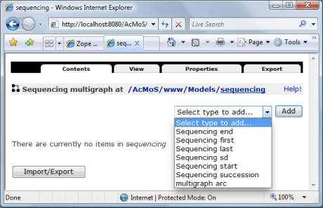
Given the CCS metamodel, transformation chain ER→Zope generates implementation of the corresponding document types for Zope. Figure 6 shows these document types as seen in CMS (see options in the drop down list). You may recognize the entities and relationships from the metamodel shown in Figure 4.

Cms_sequencing_document_types

Figure 6: Sequencing document types available in CMS

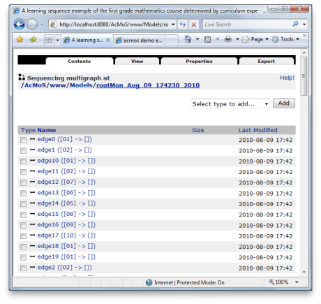
These types allow curriculum experts to build sequencing designs in a web browser. A more convenient way is to transfer sequencing designs from the DSME part. This is achieved by executing an export transformation on a sequencing design in AToM3. The result of this transformation is a fully searchable CCS document stored as graph structure in Zope. For example, given the AToM3 model in Figure 5, export would create a Zope document of type Sequencing multigraph as shown in the figure below.

Author_view_on_a_sequencing_model

Figure 7: Sequencing expert view on a CCS document

Figure 7 shows the web-interface that represents a CCS document as graph structure, i.e. a set of edges and nodes. (A viewer which can display graph-like structures in HTML web pages would be more appropriate, but is not necessary for this demo.) Note that the structure and properties of the AToM3 model from Figure 5 are transferred without loss of information.

The document shown in Figure 7 can be changed online and downloaded (via export tab seen in the screenshot) as an AToM3 model. Consequently, the downloaded file can be loaded in AToM3 for editing, thus closing the import/export round-trip.

Learning Unit Registration

Learning_unit_model

Figure 8: Learning Unit metamodel

Learning Unit is a simple and atomic Zope document type, whose AToM3 metamodel is shown in Figure 8. LU Zope type is generated and its instances are created, searched, read, and modified similar to those of the CCS document types. A simple web interface is sufficient for Material Provider. 

Obtaining Learning Routes

Currently, this service has a very basic recommendation mechanism:

  • Sequencing designs are searched to match query parameters. 
  • No account is taken of student’s curriculum competences, background and preferences (and there is no student profile). 

Searching_for_course_sequencingReader_view_on_a_sequencing_modelSubstitutive_materials_per_sd

The above screenshots illustrate the current functionality: The first is the web interface that allows students to define search parameters and displays search results. The next is the web view of the sequencing design previously shown in Figure 5. Selecting any node of the design, will display information about the sequencing node and suggest learning units and their substitutions from alternative materials providers (see the last screenshot).

Summary

In conclusion, I would like to highlight a few points about this MDE application:

The complete development of the application took about 2 man-week. The real power, however is how fast the application can be updated as the knowledge of the application domain evolves: a matter of an hour given even drastic changes in metamodels. This efficiency is possible due to application of the SSoT principle, proper abstractions and automation: Effectively, two separate PSM developments were replaced by a single PIM development, from which code is generated for two platforms (AToM3 and Zope).

In development of this application, off-the-shelf MDE frameworks were reused (namely AToM3 and ZCase) and traditional development process was interwoven with development of missing model-driven assets (metamodels, ER→ZCase transformation). The latter is a software development process too, and as a matter of fact, followed OMG’s CIM/PIM/PSM process architecture.

Naturally, development of model-driven assets has its particularities as well. For one, there is a much stronger isomorphism between objects in the world of application users and domain concepts in model-driven artifacts. Therefore, role of analysis models, such as shown in Figure 2 is more important than in the more requirements-oriented traditional development.

This demo provides extremely simplified service for learning route recommendation. Recommendation algorithm depends on the information structures and is sensitive to changes in those structures as well. The service is in fact a model interpretation, where model is a CCS design and a Student profile. A possible MDE approach to building an application-specific interpreter is described here (but be sure to read the approach’s limitations as well).

Developed metamodels reach level 5 of metamodeling quality. This topmost level means that all aspects of the language have been modeled, including its semantics. In this demo, semantics of ER was defined by using the translational approach, that is by translating ER concepts to Zope and AToM3 concepts that have precise semantics. Figure 3 shows these translations as Model→Code and Generate DSME activities. This illustrates that a language can have multiple semantics.

The demo also showed that modular transformations can be reused to form new transformation chains. Case in point is how ZCase was integrated in ER to Zope transformation by means of a relatively simple bridge. This is a counterexample to a claim that MDE solutions are inflexible.

Do you have experience with MDE applications within your organization? Can you share these experiences as well?

References

[1] Yu-Liang Chi. 2009. Ontology-based curriculum content sequencing system with semantic rules. Expert Syst. Appl. 36, 4 (May 2009), 7838-7847. 

While effort reduction and quality increase are both commonly recognized benefits of MDE, the former particularly has become its trademark, thanks to numerous generative uses in model-driven software development (MDSD). Examples include generation of code and configurations from models written in UML, DSLs and XML.

The_effort_in_mde_approach_with_partial_manual_coding

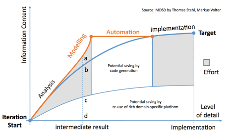
Figure: The effort in MDE approach with partial manual coding (adapted from [1])

The generative MDE automates well defined routine activities. An effective metric of depicting economical benefit thereof is effort. The above figure illustrates effort reduction due to automation and reuse in an MDE approach with partial manual coding. Of cause, the generative MDE improves quality as well: error reduction, enforced architecture conformance, and up-to-date documentation are common factors that have positive effect on software quality. But usually these are considered as icing on the cake that is effort reduction. In my experience this perspective on the economical value of MDE is common among both customers and MDE professionals. The perspective can be summarized as “the same with less”.

More with the same

Recently a client tasked me together with its domain experts to assess benefits of applying MDE to a difficult process within the organization. Having analyzed the before and after situations, we came up with estimated economical benefit expressed in effort savings. The estimate was hard to quantify, but “should” have been OK. Although I wanted to share this optimism, I felt that in practice the effort saving would be negligible if not even negative. This paradox was due to the fact that the largest activity in the problem domain was inherently creative and exploratory. 

In the figure, the output of a single exploration in this activity is shown as intermediate result, corresponding to line ad. As the figure suggests, code generation directly from the output is not possible (this happens further downstream in development). You may have noticed that the modelling curve rises more steeply towards point a. This rise occurs because modelling requires increased level of domain understanding and more information is needed by semantically rich operations, such as simulation, verification, code generation (eventually), etc. On the other hand, the figure shows effort reduction indicated by distance cd, which is the result of providing end users with proper abstractions, faster access to right knowledge, separation of concerns, DRY modelling, maintained consistency and integrity.

While working efficiency per exploration is likely to  increase (compare ab and cd), the leading concern is quality of the output. Here benefits are early detection of design errors, deep exploration of design choices, better communication and documentation, maximized reuse of domain-specific platforms in further development. Moreover, the domain experts noted that any saved effort would be re-invested in more alternative explorations in search of a more optimal output. This increased number of explorations, is likely to balance out any savings due to higher efficiency.

With these insights, economical benefits were expressed with quality metrics and linked to different business goals than initially thought.

Conclusion

The described MDE assessment targets a highly creative engineering activity that explores alternative choices. In extreme case, the main benefit is not effort reduction, but increased product and process quality. The icing on the cake is that processable models can open opportunities for generative uses as well.

In my experience, such and certainly less extreme quality-driven cases are not exotic. In recent years, quite a few MDE projects I’ve participated in, had benefits strongly linked to quality improvement. What are your MDE experiences with creative activities? What were the economical benefits and how were they conveyed?

References

[1] Thomas Stahl, Markus Voelter, Krzysztof Czarnecki. “Model-Driven Software Development: Technology, Engineering, Management”. Wiley; 1 edition (May 19, 2006)

L_from_pencils

Nowadays DSLs seem to be everywhere. If 5 years ago DSL was an exotic word in the UML dominated model driven world, today it has established a strong following. A recent research on how MDE is used in industry [1], indicated that nearly 40% of respondents use in-house DSLs (alongside of other languages). The in-house qualifier is important, as these DSLs are very likely to be developed with metamodels. In such cases, a quality benchmark may help language development. Yet, it is not easy to find such a benchmark, let alone one that is widely accepted.


Five levels of Metamodelling

One quality benchmark that I found useful is described by Tony Clarks et. al in [2]. The authors define 5 levels of quality. These briefly are:

  1. The lowest level: a simple abstract syntax is defined, but not implemented yet in a tool. The static and dynamic semantics of the language is informal and incomplete. There is no specific tool support: an existing language is repurposed, compliance with the DSL is manually maintained and models are mostly interpreted by users.
  2. At this level, the abstract syntax and static semantics have been largely defined, implemented in a tool and validated. The dynamic semantics is still informally defined.
  3. The abstract syntax is completely implemented and tested. Concrete syntax has been defined for the language, but not implemented yet. Optimization of the language architecture has started.
  4. The concrete syntax of the language has been implemented and tested. Users create models either visually and textually. The language architecture has been optimized for reuse and extensibility. Tool support for dynamic semantics begins to appear.
  5. The topmost level: all aspects of the language have been modeled, including its semantics. Models written in the language can be processed by the tool. Examples thereof include code generation, execution, simulation, verification. The language architecture is well optimized for reuse.

While the original intention of the benchmark was to assess metamodels, I found it also useful for estimating metamodelling capabilities of MD tools. If a tool is not capable of supporting development needs for a certain level, then that level will be the quality ceiling for all metamodels defined with the tool. In my experience, DSLs in traditional (fixed method) CASE Tools do not achieve level greater than 1. Metamodels in UML tools often do not reach level 4 (and often lack static semantics and concrete syntax). Language workbenches can typically produce level 5 metamodels.

Conclusion

The referenced benchmark provides a first order approximation of quality of metamodels. Furthermore, these 5 levels provide those looking for MDx technology, with a simple framework at least to question the marketing information by tool vendors. In my opinion this benchmark may be a useful ingredient in an answer to a more general question of comparing MD technologies.

What are your experiences with measuring quality of metamodels or comparing metamodelling capabilities of MDx tools? Which aspects are you interested in and how do you measure them?

References

[1] John Hutchinson, Mark Rouncefield, Jon Whittle, and Steinar Kristoffersen. Empirical Assessment of MDE in Industry. ICSE 2011.

[2] Tony Clark, Andy Evans, Paul Sammut, and James Willans. Applied Metamodelling: A foundation for Language Driven Development. Version 0.1. Xactium Ltd., 2004.

Image by Aqua

Blogs by Johan den Haan, Stefano Butti and Jordi Cabot raised interesting discussions about code generation (CG) and model interpretation (MI). One observation I took from these discussions is that MI is still little known. Previously I demonstrated operation of a custom-made model interpreter for a so-called weighbridge domain. Today I would like to share my experience of building this interpreter in a model-driven way.

MDE Approach

Two main choices underpin the process and technology used to develop the interpreter:

  1. Execution semantics of the interpreter is defined within the problem domain itself (weighbridge in this case), without translating it to another domain (e.g. .Net or Java) as it is the case with CG. Such definition of semantics is also known as operational semantics. The advantage is reduction of development complexity: out of at least 2 domains needed for CG, only one and the more abstract domain is sufficient.
  2. Operational semantics is defined within an MDE framework. This enables customization of modeling language for problem domains besides that of the weighbridge example. Moreover, transformation capabilities are used to define operational semantics. 

Domain-specific_nested_interpretation_mde_framework

Figure 1: Domain-specific, nested interpretation (DSNI) MDE framework

Figure 1 shows the MDA framework [1] after it has been adapted to reflect the above mentioned choices. (If you are confused between MDA and MDE, you might find this article useful.) In contrast to MDA, there is no PIM or PSM model, but single computational independent model (CIM) written in DSL. CIM is both source and target of Transformation Tool. Transformation Tool carries out transformation classified as same language, same model. Transformation Definition defines operational semantics. It is not important if Transformation Definition Language (TDL), extends the Metalanguage as in MDA or is customizable by means of meta-specification. Therefore TDL is omitted from the framework and TDL selection criteria are defined instead (see below). Finally, new concept System Context is connected to Transformation Tool. This is due to the fact that interpretation as system exhibits external behavior through communication with other systems.

This approach can be described as nested interpretation, where a domain-specific interpreter is executed (nested) by a generic interpreter. From this perspective, Transformation Tool assumes the role of a generic interpreter and execution of Transformation Definition fills in the role of the domain-specific interpreter.

TDL Selection Criteria

Selection criteria for transformation definition language are:

  • declarative modeling 
  • support for domain-specific notation

These criteria help to reduce development complexity and improve communication with problem domain experts.

Selected MD Technology

AToM3 is a free language workbench written in Python and under development at the Modelling, Simulation and Design Lab (MSDL) in the School of Computer Science of McGill University. The workbench closely matches the DSNI framework and meets the TDL selection criteria. 

In AToM3, DSLs and models are described as graphs. From a language specification written in the metalanguage (ER formalism), AToM3 generates a tool to visually manipulate (create and edit) models written in the specified DSL. Model transformations are performed by graph rewriting. The transformations themselves can thus be declaratively expressed as graph-grammar models. However, AToM3 provides no communication infrastructure as needed by the framework.

Proof of Concept

As demonstration, a language specification for the weighbridge domain was defined (see sections domain and weighbridge DSL here) and graph rewriting was used to model operational semantics (see below). Source code of AToM3 itself, being written in Python, was extended to support web services for the communication purpose.

Operational Semantics

As blueprint for operational semantics of the interpreter, we took πDemos [2], a small process-oriented discrete event simulation language. There is a number of πDemos events that change state of a weighbridge system. For each such event, [2] defined the transitions induced on system state. While the original used functional programming language, this work uses graph rewriting and a graph grammar (GG) rule is defined per event.

Priority GG Rule Description
50 importProcess Adds an external vehicle to EL
25 removeProcess Deletes a vehicle that has completed its todos (events)
40 newR Creates a new weighbridge
40 decP Creates a new vehicle class
40 newP Creates a vehicle from a vehicle class
40 getR Acquires a non-busy weighbridge
40 blockProcess Blocks a vehicle acquiring a busy weighbridge
40 promoteProcess Unblocks a delayed vehicle
40 useR Moves a vehicle on a weighbridge until service is complete
30 releaseResource Moves a served vehicle from a weighbridge to EL
41 putR Releases an occupied weighbridge

Table 1: Graph grammar rules of weighbridge events

Table 1 lists the minimum set of required events and their corresponding GG rules. Execution of such rules needs to be globally orchestrated through proper sequencing. The rules, together with execution sequencing, form an operational semantics model of the interpreter. 

For complete description of the model, please refer to [3]. In the following, we present a detailed description of an example rule, followed by the execution sequencing model.

Example GG Rule

LhsRhs

Figure 2: Subgraphs of the promoteProcess rule

Rule promoteProcess releases a busy weighbridge (bluish box in Figure 2.1) that delays at least one vehicle (yellow box labelled 5). In the new state, the weighbridge remains busy and the blocked vehicle (5) is removed from the head of queue Delay and inserted in waiting queue EL.

The rule is executed if:

  1. The left-hand side (LHS) shown in Figure 2.1 is matched in the host graph (the CIM model).
  2. Associated condition is true: the weighbridge in LHS is the one referred to in the imminent event putR (a todo) in the body (a todo list) of the first vehicle (label 21) in queue EL.

If the above holds, the matched part of the CIM model is substituted with the right-hand side (RHS) shown in Figure 2.2. Note new objects are labelled 10, 11, 13. The entities and relationships in RHS are initialized as follows:

  1. Objects copied from LHS keep all their properties. 
  2. Imminent event putR (a todo)  of the current vehicle (21) is completed. 
  3. All properties of blocked vehicle (5) are copied to vehicle (10).

Execution Sequencing

The execution sequencing is based on the next-event approach: Next event to execute is always the imminent event in the body of the current vehicle. Informally, the operational semantics of execution sequencing is as follows: if EL is empty, interpreter idles until at least one vehicle is inserted in EL. Such vehicle becomes current. If the body of the current vehicle is empty then it is removed from EL and EL is examined again. Otherwise, interpreter  executes a GG rule corresponding to the imminent event of the current and EL is examined again. Note that whenever interpreter is idle, EL is being updated with new vehicles that meanwhile might have arrived from system context.

The execution sequencing is implemented by organizing GG rules into groups, each group having its own base priority. These groups, in the descending order of priority are: vehicle removal, weighing activities and vehicle arrival. Within a group, each rule is assigned a relative priority. If pattern matching of two and more rules within a group is deterministic on the basis of LHSs and conditions, then these rules can share the same priority level. Example rule priorities are given in Table 1.

Conclusion

The demonstrated development approach is characterized by a very high level of abstraction, direct involvement of problem domain experts and absence of software development. All these factors contribute to fast development times: The lead time of this one man project including research and development was 3 weeks. Admittedly, tests of the produced model interpreter showed noticeable performance penalty due to 1) repurposing of MD technology that was not designed for use as interpreter and 2) the overhead introduced by nested interpretation. In my opinion there is much room for performance improvement and I am wondering if MDE can prove useful again. An important message from this experience is that model interpretation does not have to be prerogative of big commercial tools and can get closer to code generation in terms of accessibility.

References

[1] Anneke G. Kleppe, Jos Warmer and Wim Bast. “MDA Explained: The Model Driven Architecture: Practice and Promise”. Addison-Wesley Longman Publishing Co., Inc., Boston, MA, USA, April 2003.

[2] Graham Birtwistle and Chris Tofts. “An operational semantics of process-oriented simulation languages: Part 1 πDemos”. ACM Transactions on Modeling and Com- puter Simulation, 10(4):299–333, December 1994.

[3] Andriy Levytskyy. “Model Driven Construction and Customization of Modeling & Simulation Web Applications”. PhD thesis, Delft University of Technology, Delft, The Netherlands, January 2009.